Methods and apparatus to position a mobile receiver using downlink signals part IV

a mobile receiver and signal technology, applied in direction finders, transmission, wireless communication, etc., can solve the problems of limiting the performance of ct location estimation and radio signal interference with one another

Inactive Publication Date: 2001-07-24
CELL LOC LOCATION TECH
View PDF72 Cites 268 Cited by
  • Summary
  • Abstract
  • Description
  • Claims
  • Application Information

AI Technical Summary

Problems solved by technology

Radio signals can interfere with one another unless multiple access techniques are employed.
These assignment algorithms will limit the performance of estimation of the CT location, as they will often ignore pilot signals useful for the location estimation.

Method used


Image

  • Methods and apparatus to position a mobile receiver using downlink signals part IV
  • Methods and apparatus to position a mobile receiver using downlink signals part IV
  • Methods and apparatus to position a mobile receiver using downlink signals part IV

Examples


Embodiment Construction
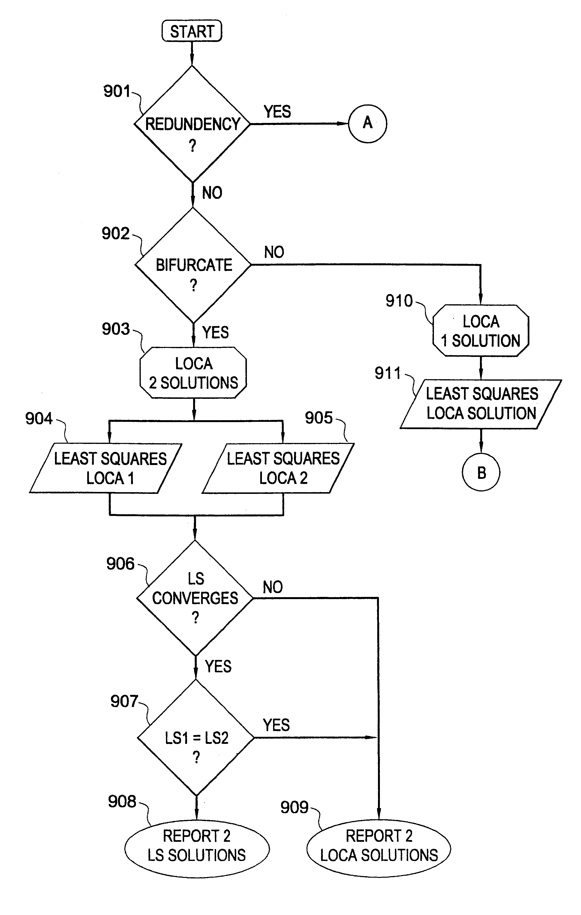
Theory:

In a WLS, many factors affect the system performance:

1. RF shadowing and flat fading,

2. frequency offsets (including LOs drift and Doppler Shifts),

3. clock errors,

4. time delays,

5. noise,

6. multipath (selective fading),

7. interference;

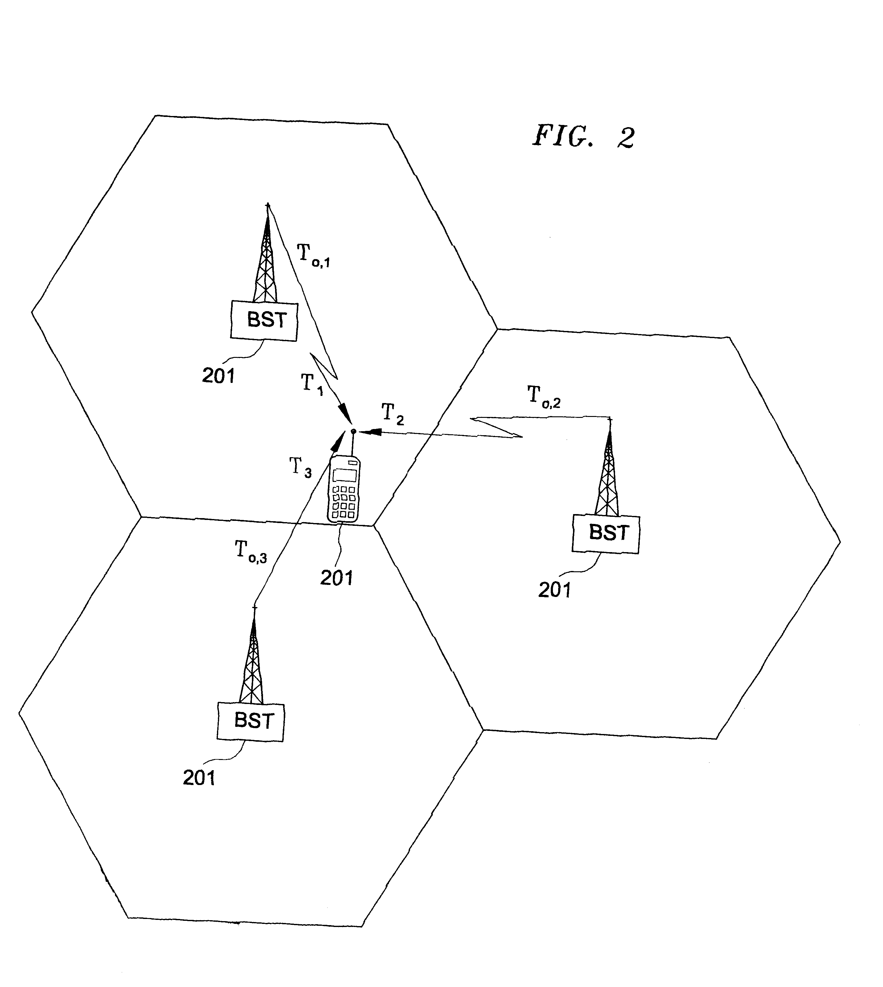
8. geographical geometry of the BSTs relative to the intended MR.

Each factor degrades the estimate location of the MR depending on the technology employed for extracting the independent equations required for location.

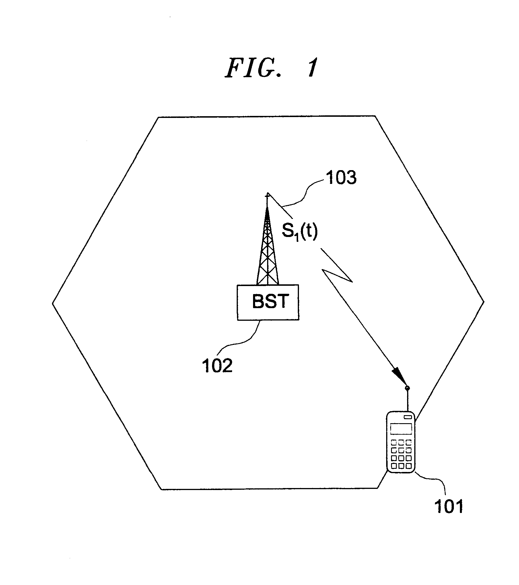
RF Transmission: More specifically, the Low Pass (LP) equivalent signal, s.sub.i (t), transmitted from the i.sup.th BST can be modeled as

s.sub.i (t)=e.sup.-j2.pi.(f.sup..sub.c .sup.+.DELTA.f.sup..sub.i .sup.).tau..sup..sub.o,i e.sup.j(2.pi..DELTA.f.sup..sub.i .sup.t+.zeta..sup..sub.i .sup.) p.sub.i (:t-.tau..sub.o,i) (3)

and the RF transmitted signal, s.sub.i (t), (see FIG. 1) can be expressed as

s.sub.i (t)=Re{e.sup.j2.pi.f.sup..sub.c .sup.t s.sub.i (t)} (4)

where

Re{.} denotes a real part operation;

f.sub.c is the carrier frequency,

.D...


PUM


Abstract

The invention consists of methods and apparatus to estimate the position and velocity of a Mobile Receiver (MR) using either the Time Of Arrival (TOA) of signals received by the MR, their Phase Of Arrival (POA), their Strength Of Arrival (SOA), their Frequency Of Arrival (FOA), or a combination thereof, with respect to a reference produced by a Reference Receiver (RR) of known location. In order to solve for the coordinates of the MR, the invention uses either hyperbolic multilateration based on Time Difference Of Arrival (TDOA), or linear multiangulation based on Phase Difference Of Arrival (PDOA), or both. In order to solve for the velocity of the MR, the patent uses FOA based on Frequency Difference Of Arrival (FDOA).

Description

This invention relates to location finding and tracking of a Mobile Receiver (MR) using a Reference Receiver (RR) of known location.Whenever a number of signals are available for reception to the MR as well as to the RR, it is possible to locate the MR. Examples of radio signals that exist with worldwide coverage are satellite signals such as Global Positioning System (GPS), Iridium, Gobalstar, etc. Examples of radio signals that can penetrate structures such as buildings are land-based systems such as cellular, PCS, paging, and ESMR, among others. Both satellite-based signals and terrestrial-based signals can be sued to located the MR by relying on their reception at both the MR and the RR. In this patent, we refer to such a location system as a handset-based Wireless Location System (WLS) (or Forward / downlink-based WLS), as opposed to a network-based WLS (or Reverse / uplink-based WLS), which locates a Mobile Transmitter (MT) using a plurality of receivers that receive the signal tr...

Claims


Application Information

Patent Timeline
Patent Type & Authority Patents(United States)
IPC IPC(8): G01S5/00G01S5/14G01S5/08G01S5/10G01S5/12H04Q7/38G01S19/14H04W24/00H04W64/00
CPCG01S5/0009H04W64/00G01S5/08G01S5/10G01S5/12H04W64/006G01S2205/008H04W24/00G01S5/14
Inventor FATTOUCHE, MICHELKLUKAS, RICHARDOLER, KEVIN
Owner CELL LOC LOCATION TECH
Why Eureka
Try Eureka