Consequently, according to the third embodiment, even in the case of utilizing a scanning lens in which the detection lens 1 is employed for light writing-in, basically, the measurement system can be set to a state of
actual use utilizing a structure capable of optionally setting the distance between the detection lens 1 and the lens 9. In addition, the angle of the unitary combination of the polarization plate 15, etc. with respect to the advancing direction of the transmission light transmitted through the detection lens 1 is adjusted, and thereby the light can be directed almost vertically as the incident light. In such a structure, further precise measurements can be performed.
To state the operation more strictly in this connection, even in the partial measurement area capable of observing once, the advancing angle of the light rays differs to some extent in accordance with the place. However, the rotative stage 35 is rotated such that the element surface of the polarization plate 15 may become vertical (perpendicular or opposed) to the average advancing direction of the light rays from the
optical axis of the optical system. Thereby, it is possible to perform the measurement with a small error occurrence. Furthermore, as to the advancing angle of the light rays from the
optical axis of the optical system, for instance, since the angle is previously obtained every lens height of the detection lens 1 after passing through the detection lens 1 utilizing the light pursuing
simulation, it is preferable to obtain the advancing angle of the average light rays in a partial area to be measured on the basis of the shape of the detection lens 1 or the setting of the measurement optical system. Furthermore, in the case of employing detection lenses respectively having different curvatures in the main scanning direction and in the subscanning direction, it is also preferable to further provide a
flapping mechanism on the base 31 in addition to the rotation mechanism such as the rotation stage 35 and to three-dimensionally perform the same operation as mentioned above.
Consequently, according to the third embodiment, even in the case of utilizing a scanning lens in which the detection lens 1 is employed for light writing-in, basically, the measurement system can be set to a state of
actual use utilizing a structure capable of optionally setting the distance between the detection lens 1 and the lens 9. In addition, the angle of the unitary combination of the polarization plate 15, etc. with respect to the advancing direction of the transmission light transmitted through the detection lens 1 is adjusted, and thereby the light can be directed almost vertically as the incident light. In such a structure, further precise measurements can be performed.
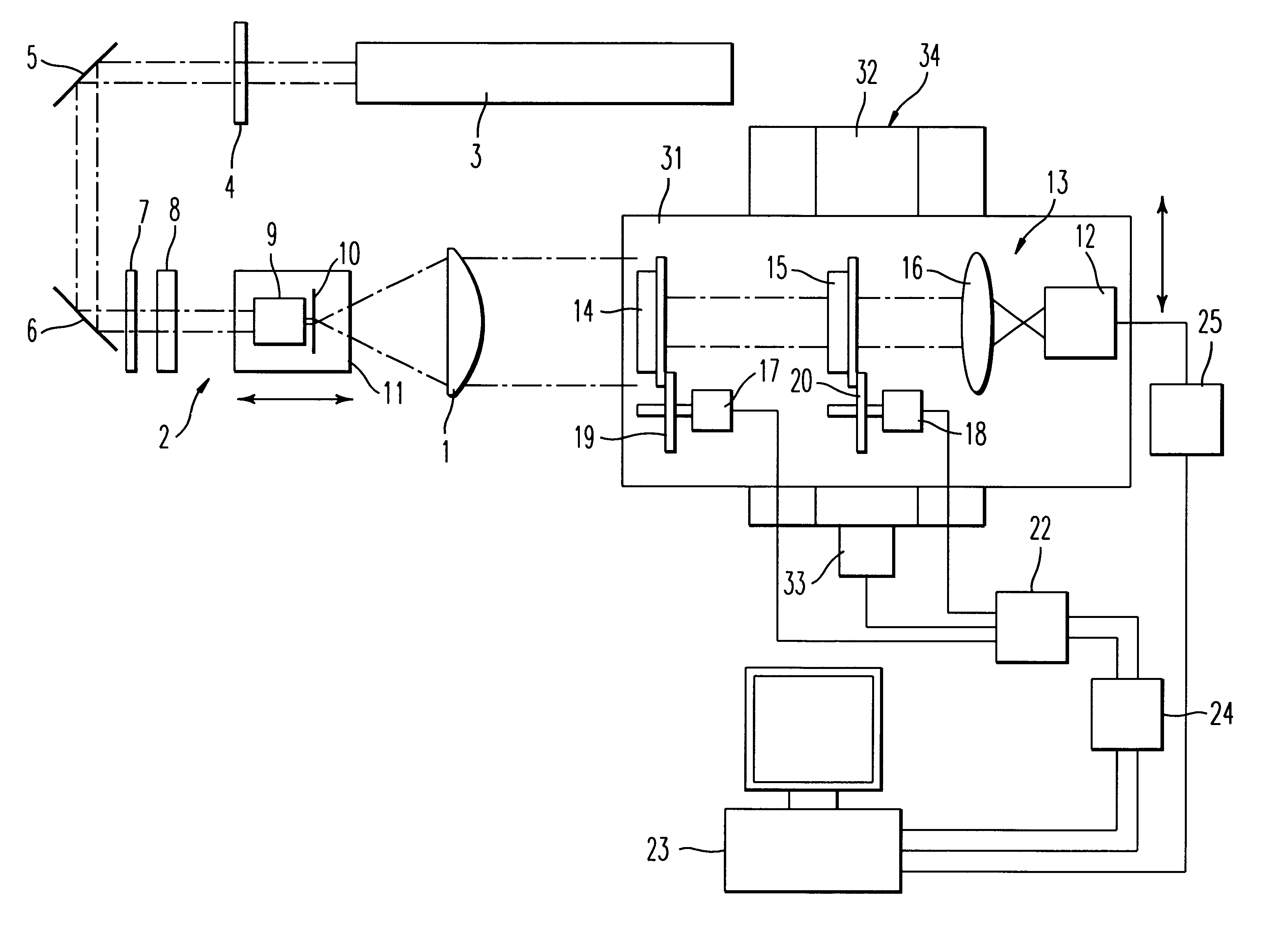
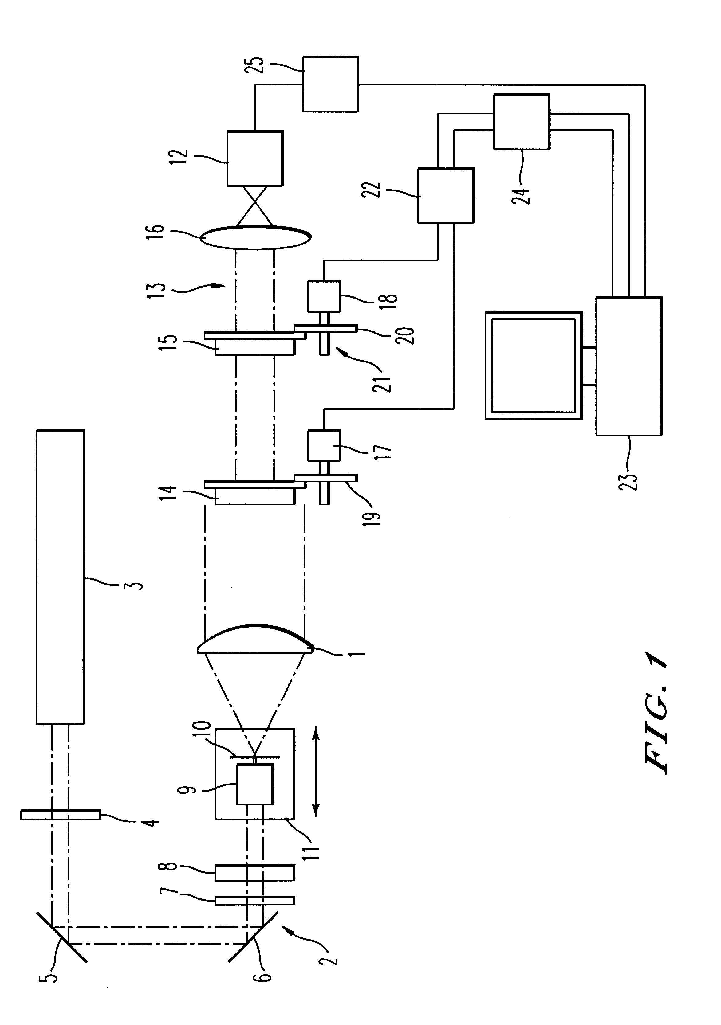
In the birefringence measuring apparatus and method of the invention as a feature, in a manner basically according to the rotative analyzer method, the transmission light transmitted through the detection lens is directed to the polarization element for changing the polarization state as the incident light. Rotating the polarization element, the light is received and detected by the array state light-receiving element, and thereby the birefringence of the detection lens is calculated. In such a situation, the distance between the
radiation optical system for radiating the
diffusion light onto the detection lens and the detection lens can be optionally set. Observing the
transmission image transmitted through the detection lens, the distance between the detection lens and the radiation optical system is adjusted. Thereby, it is possible to obtain optical elasticity interference fringes of the
transmission image of the detection lens 1 which at most are only slightly affected by
optical distortion. Furthermore, the measurement of the birefringence can be precisely performed over the entire surface of the detection lens 1. At the same time, it is possible to easily cope with a change of a type of the detection lens. In such a way, a widely-
usable apparatus for and method of measuring the birefringence can be realized.
Consequently, according to the third embodiment, even in the case of utilizing a scanning lens in which the detection lens 1 is employed for light writing-in, basically, the measurement system can be set to a state of actual use utilizing a structure capable of optionally setting the distance between the detection lens 1 and the lens 9. In addition, the angle of the unitary combination of the polarization plate 15, etc. with respect to the advancing direction of the transmission light transmitted through the detection lens 1 is adjusted, and thereby the light can be directed almost vertically as the incident light. In such a structure, further precise measurements can be performed.
Consequently, according to the third embodiment, even in the case of utilizing a scanning lens in which the detection lens 1 is employed for light writing-in, basically, the measurement system can be set to a state of actual use utilizing a structure capable of optionally setting the distance between the detection lens 1 and the lens 9. In addition, the angle of the unitary combination of the polarization plate 15, etc. with respect to the advancing direction of the transmission light transmitted through the detection lens 1 is adjusted, and thereby the light can be directed almost vertically as the incident light. In such a structure, further precise measurements can be performed.
In the birefringence measuring apparatus and method of the invention as a feature, in a manner basically according to the rotative analyzer method, the transmission light transmitted through the detection lens is directed to the polarization element for changing the polarization state as the incident light. Rotating the polarization element, the light is received and detected by the array state light-receiving element, and thereby the birefringence of the detection lens is calculated. In such a situation, the distance between the radiation optical system for radiating the
diffusion light onto the detection lens and the detection lens can be optionally set. Observing the transmission image transmitted through the detection lens, the distance between the detection lens and the radiation optical system is adjusted. Thereby, it is possible to obtain optical elasticity interference fringes of the transmission image of the detection lens 1 which at most are only slightly affected by
optical distortion. Furthermore, the measurement of the birefringence can be precisely performed over the entire surface of the detection lens 1. At the same time, it is possible to easily cope with a change of a type of the detection lens. In such a way, a widely-
usable apparatus for and method of measuring the birefringence can be realized.
In the birefringence measuring apparatus and method of the invention as a feature, in a manner basically according to the rotative analyzer method, the transmission light transmitted through the detection lens is directed to the polarization element for changing the polarization state as the incident light. Rotating the polarization element, the light is received and detected by the array state light-receiving element, and thereby the birefringence of the detection lens is calculated. In such a situation, the distance between the radiation optical system for radiating the diffusion light onto the detection lens and the detection lens can be optionally set. Observing the transmission image transmitted through the detection lens, the distance between the detection lens and the radiation optical system is adjusted. Thereby, it is possible to obtain optical elasticity interference fringes of the transmission image of the detection lens 1 which at most are only slightly affected by optical
distortion. Furthermore, the measurement of the birefringence can be precisely performed over the entire surface of the detection lens 1. At the same time, it is possible to easily cope with a change of a type of the detection lens. In such a way, a widely-
usable apparatus for and method of measuring the birefringence can be realized.
