Supercharge Your Innovation With Domain-Expert AI Agents!

Low cost shallow trench isolation using non-conformal dielectric material

Inactive Publication Date: 2001-08-07
GLOBALFOUNDRIES INC
View PDF15 Cites 19 Cited by
  • Summary
  • Abstract
  • Description
  • Claims
  • Application Information

AI Technical Summary

Problems solved by technology

Two major challenges in achieving the shallow trench isolation (STI) structure are: (1) filling the narrow trenches without voids or seams defect, and (2) planarization of trenches of diverse widths.
The seams become a major problem as the device dimensions scale downward and the aspect ratio of the STI increases.

Method used


Image

  • Low cost shallow trench isolation using non-conformal dielectric material
  • Low cost shallow trench isolation using non-conformal dielectric material
  • Low cost shallow trench isolation using non-conformal dielectric material

Examples


Embodiment Construction

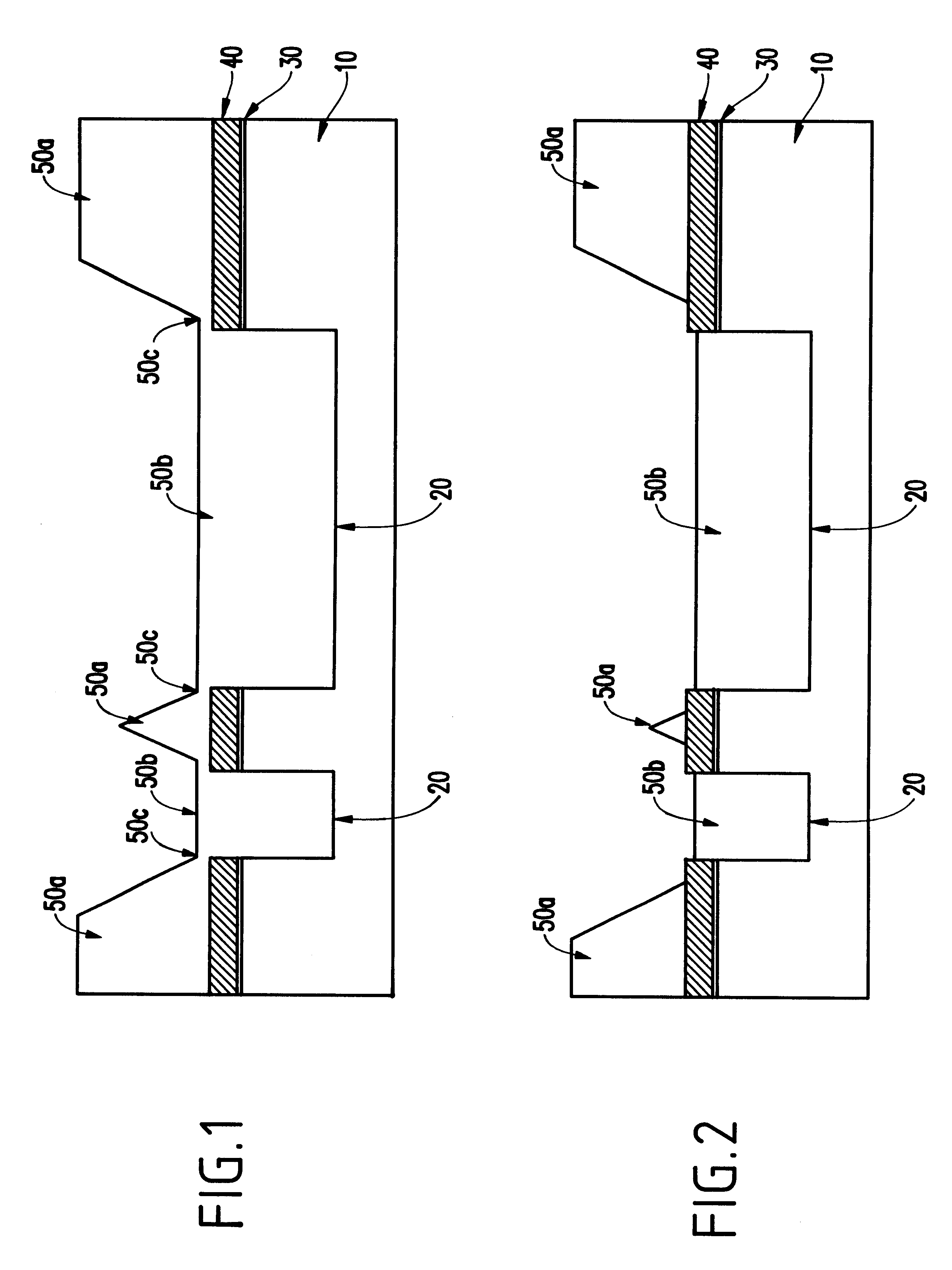
FIG. 1 shows a preferred method of forming a shallow trench isolation (STI) region using non-conformal dielectric material such as non-conformal high density plasma oxide. In this method, a silicon substrate 10 is initially provided and an oxide pad 30 and a nitride pad 40 are then formed over silicon substrate 10. A trench region 20 is then formed into the silicon substrate 10 in a conventional manner. Normally the trench region 20 is delineated by 1) applying a thin coat of photoresist on the wafer, 2) exposing selected regions of the photoresist to light in order to induce a chemical change in the photoresist, and 3) removing the exposed portions of the photoresist by wet-chemical means. Then the exposed regions of the wafer are removed to a desired depth using an anisotropic subtractive etch process. Conventional and appropriate subtractive etch methods include reactive ion etching, which is also known as plasma etching or dry etching. Such an etch process normally exhibits high...


PUM


Abstract

A method is provided for planarizing a structure such as a shallow trench isolation region on a semiconductor substrate. A semiconductor substrate is provided having raised and lowered regions with substantially vertical and horizontal surfaces. The lowered regions may correspond to trench regions. Filler material such as non-conformal high density plasma oxide may be deposited over the horizontal surfaces to at least a thickness equal to a predetermined height so as to provide raised and lowered regions of the filler material. The raised regions of the filler material may then be selectively removed without removing the filler material in the lowered regions.

Description

1. Field of the InventionThe present invention generally relates to a process to form planarized shallow trench isolation structures using a non-conformal high density plasma (HDP) oxide deposition.2. Description of the Related ArtIntegrated circuits are formed from semiconductor substrates within and upon whose surfaces are formed resistors, transistors, diodes and other electrical circuit elements. The electrical circuit elements are connected internally and externally to the semiconductor substrate upon which they are formed through patterned conductor layers which are separated by dielectric layers.As integrated circuit device technology has advanced and integrated circuit device dimensions have decreased, it has become increasingly common within advanced integrated circuits to employ trench isolation methods such as shallow trench isolation (STI) methods and recessed oxide isolation (ROI) methods to form trench isolation regions nominally co-planar with adjoining active semicon...

Claims


Application Information

Patent Timeline
IPC IPC(8): H01L21/762H01L21/70
CPCH01L21/76229
Inventor ANDREWS, JOHN W.HWANG, BAO T.LANDIS, HOWARD S.MEI, SHAW-NINGTYLER, JAMES M.VISHNESKY, EDWARD J.
Owner GLOBALFOUNDRIES INC
Features
  • R&D
  • Intellectual Property
  • Life Sciences
  • Materials
  • Tech Scout
  • Unparalleled Data Quality
  • Higher Quality Content
  • 60% Fewer Hallucinations
Learn More