Plasma torch head and method for making the same

a technology of plasma torch and torch head, which is applied in plasma technique, manufacturing tools, welding apparatus, etc., can solve the problems of limited limited useful life of torch head, so as to improve the resistance to sloughing and fracturing

Inactive Publication Date: 2001-08-07
THERMACUT KS
View PDF7 Cites 36 Cited by
  • Summary
  • Abstract
  • Description
  • Claims
  • Application Information

AI Technical Summary

Benefits of technology

It is an object of the present invention to provide a plasma torch head having improved resistance to sloughing and fracturing.
FIG. 3 is an exploded isometric view of the embodiment of FIG. 1. In addition to housing the core and transfer components, channels are provided in the shell for mounting safety switches which are closed, allowing a current to pass through the torch, when the pins are depressed. Having the shell rigid facilitates the mounting of these switches as well as providing a scuff resistant exterior to protect the torch head from abrasion and prevent any sloughed material separating from the core.

Problems solved by technology

For torch heads formed of heat resistant phenolic molding material, the life of the torch head is typically limited by fracturing of the torch head which is caused by abrasion of the surface in combination with thermal cycling of the torch head during use.
While the life of the multi-part torch head is greater than the life of the single part torch head, the resulting torch heads still suffer limited useful lives due to fracturing.
The '185 patent notes that the fabrication of housings from silicone rubber, which is one of the preferred elastomers for heat resistance, is particularly difficult since the flow characteristics of the silicone rubber are poor.

Method used


Image

  • Plasma torch head and method for making the same
  • Plasma torch head and method for making the same
  • Plasma torch head and method for making the same

Examples


Embodiment Construction

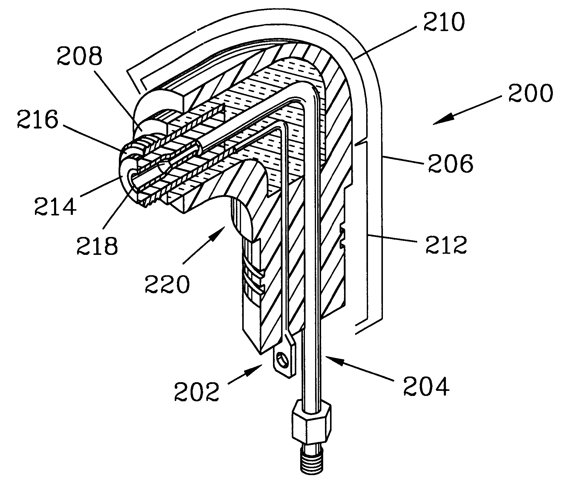
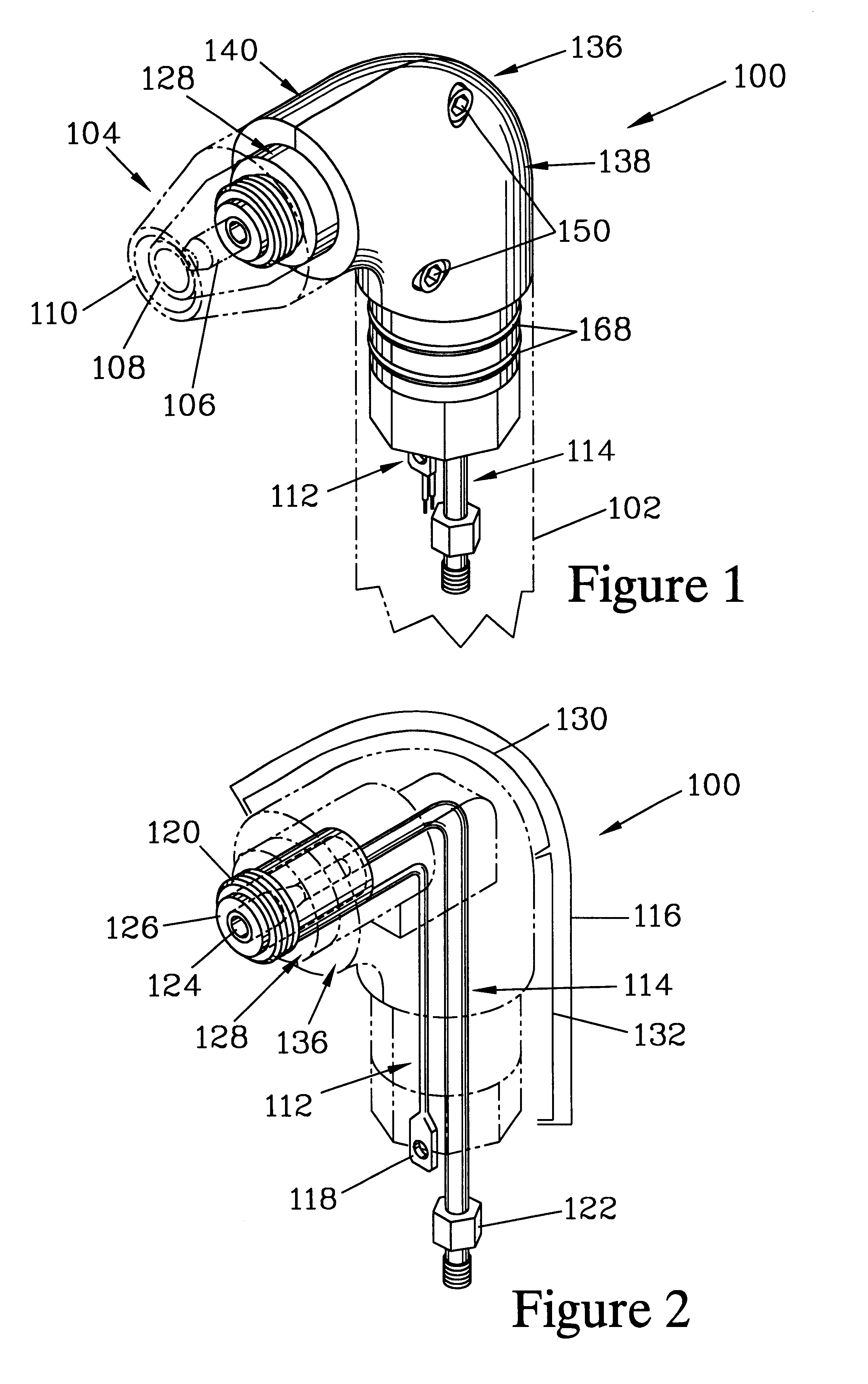
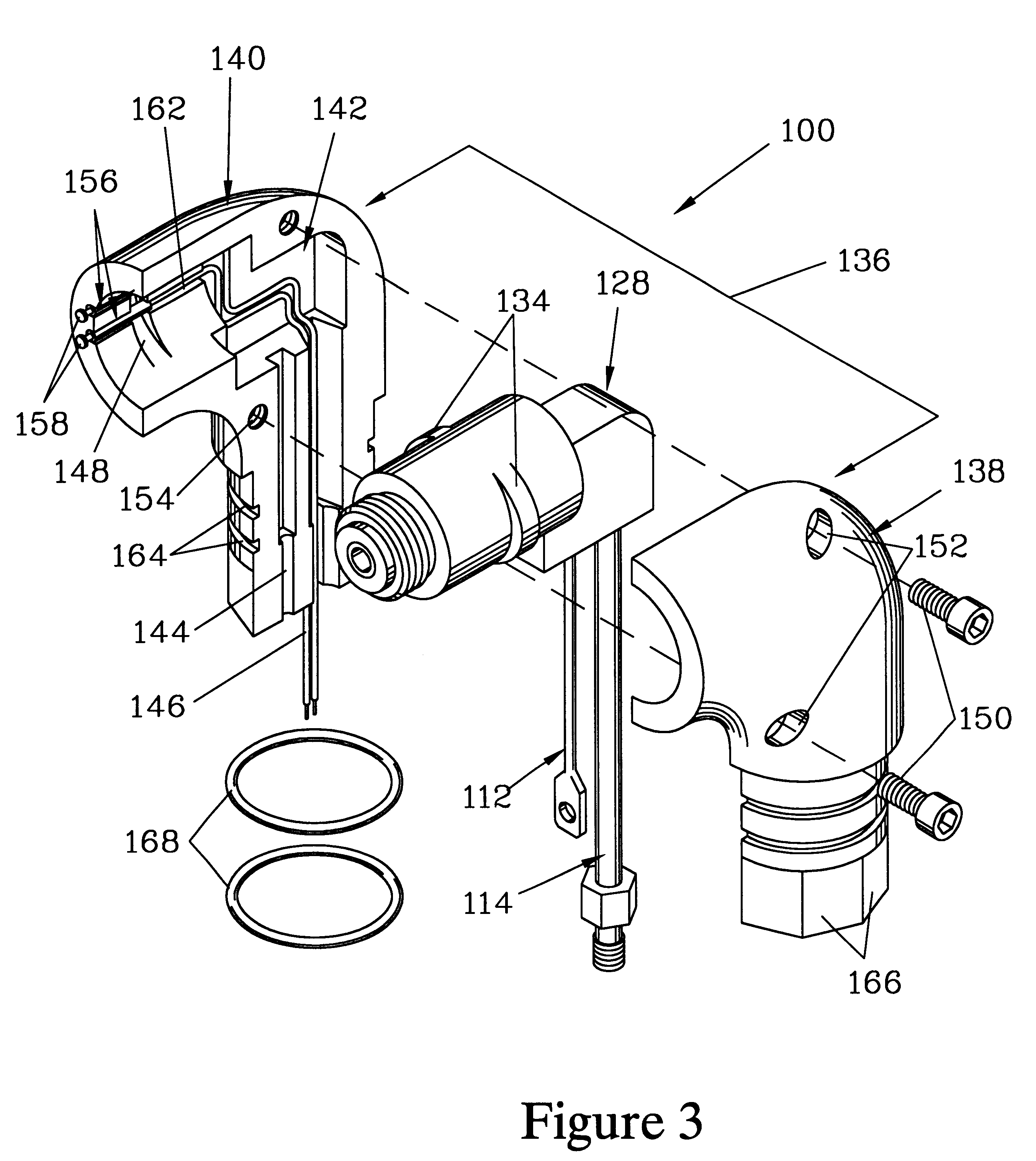
FIGS. 1 through 3 illustrate one embodiment of the present invention, a plasma torch head 100. FIG. 1 shows the plasma torch head 100 fully assembled, while FIG. 3 shows an exploded view of the plasma torch head 100. In use, the plasma torch head 100 is interposed between a torch handle 102 and a set of terminal components 104, both of which are conventional elements and are indicated in phantom in FIG. 1. The terminal components 104 include an electrode 106, a tip 108, and a shield cup 110.

The plasma torch head 100 has a HF lead 112 and a power lead / gas conduit 114 which serve to convey current and fluids from the torch handle 102 to the terminal components 104. The HF lead 112 and the power lead / gas conduit 114 serve as transfer components, and are similar to those found in conventional plasma torch heads. As best shown in FIG. 2, the HF lead 112 and the power lead / gas conduit 114 are, in part, overlapped to form an overlapping region 116. The HF lead 112 terminates in a HF lead c...


PUM

PropertyMeasurementUnit
diameteraaaaaaaaaa
diameteraaaaaaaaaa
temperatureaaaaaaaaaa

Abstract

A plasma torch head has transfer components, including an HF lead and a power lead / gas conduit, which are partially encased in a core fabricated from an elastomer. The core is housed in a rigid shell, which preferably also engages a portion of the transfer components. The shell can be a two-piece shell which is assembled around the core, or can be a single piece cast around the core. The core can be fabricated by securing the transfer components in a mold and filling the mold with an elastomer such as liquid silicone rubber. After curing the elastomer in the mold, the core is stripped from the mold and the shell is formed around the core. In one preferred method, sections of a two-part shell are injection molded from phenolic, placed about the core, and secured together with bolts. In another preferred method, the core is placed in a mold and the mold is filled with a liquid two-part epoxy which is cured in a reduced pressure atmosphere to form a one-piece shell.

Description

The present invention relates to plasma torches, and more particularly to a sloughing and fracture resistant plasma torch head and a method for making the same.Plasma torches are frequently used for welding, hard facing, and cutting metals. These plasma torches have a torch head, to which a torch handle and a set of terminal components such as an electrode, a tip, and a shield cup are attached. The torch head has embedded therein various components for transferring fluids and electrical currents, which include a high frequency (HF) lead and a power lead / gas conduit. The power lead / gas conduit is separated from the HF lead by an insulating member. The torch head is fabricated from an electrically insulating and heat resistant material which is either a phenolic molding material or an elastomer such as a rubber compound. The torch head is typically formed by molding under pressure with the other components embedded therein.For torch heads formed of heat resistant phenolic molding mate...

Claims


Application Information

Patent Timeline
Patent Type & Authority Patents(United States)
IPC IPC(8): H05H1/26H05H1/34
CPCH05H1/34H05H2001/3478H05H1/3478
Inventor ZAPLETAL, JIRI
Owner THERMACUT KS
Why Eureka
Try Eureka