
Device for measuring the mass of a flowing medium

a technology of flowing medium and measuring device, which is applied in the direction of liquid/fluent solid measurement, volume metering, instruments, etc., can solve the problems of limiting the engineering and design possibilities, and affecting the accuracy of measurement results

Inactive Publication Date: 2001-08-14
ROBERT BOSCH GMBH
View PDF4 Cites 25 Cited by
  • Summary
  • Abstract
  • Description
  • Claims
  • Application Information

AI Technical Summary

Benefits of technology

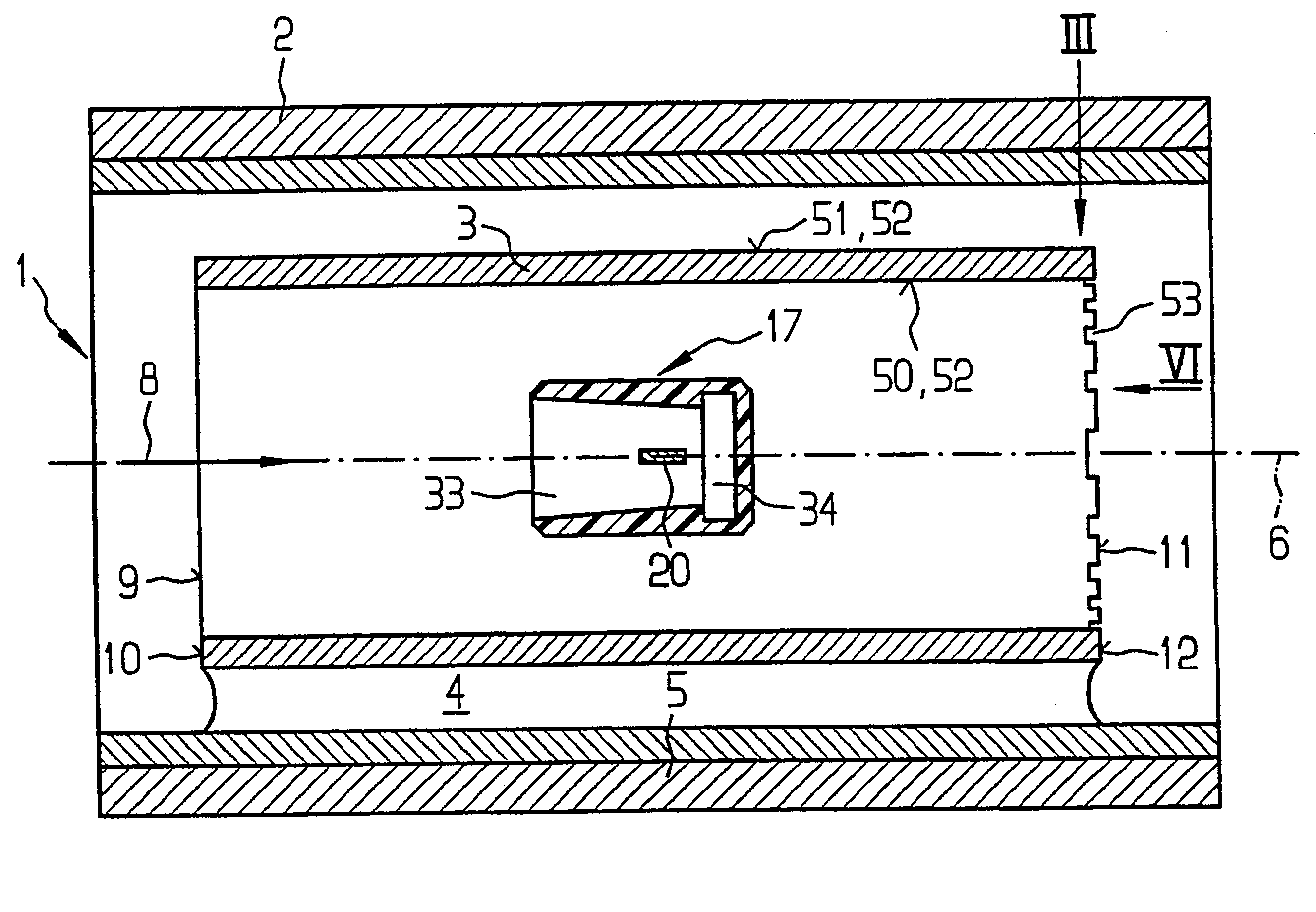
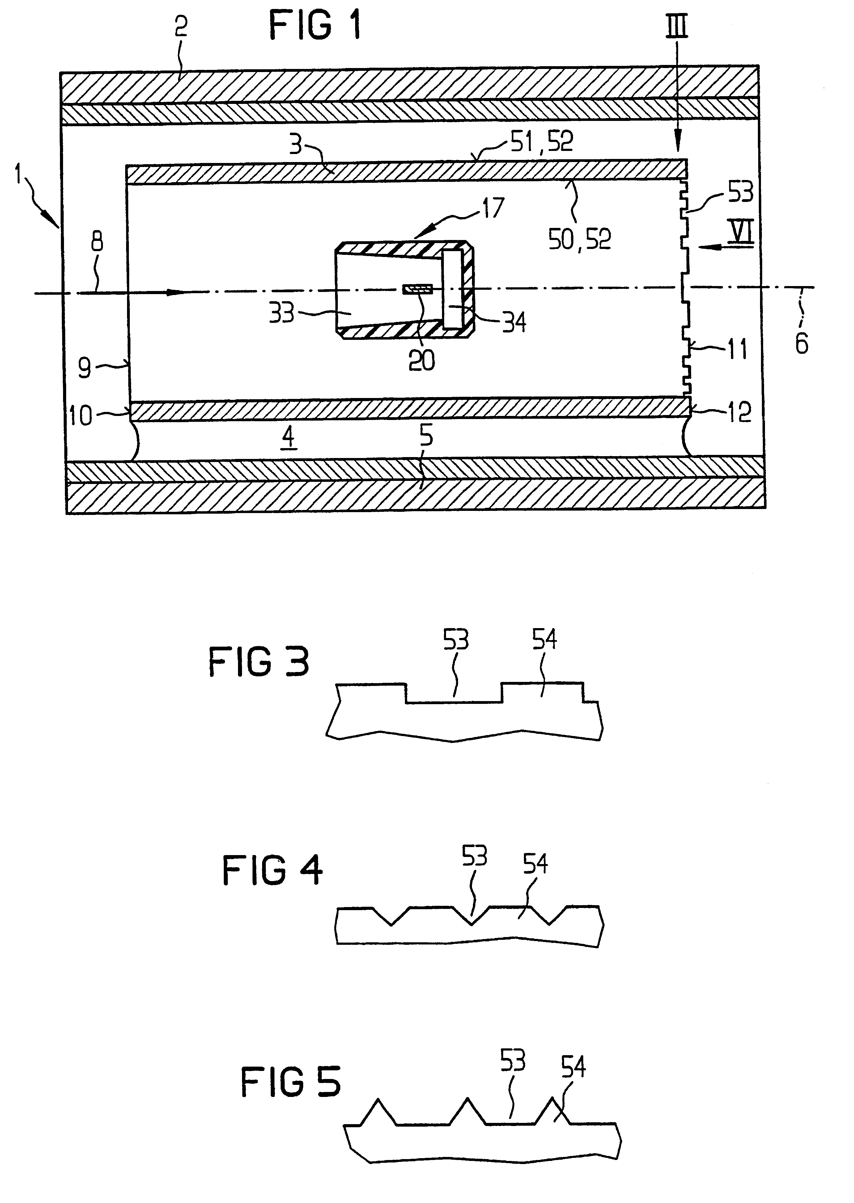
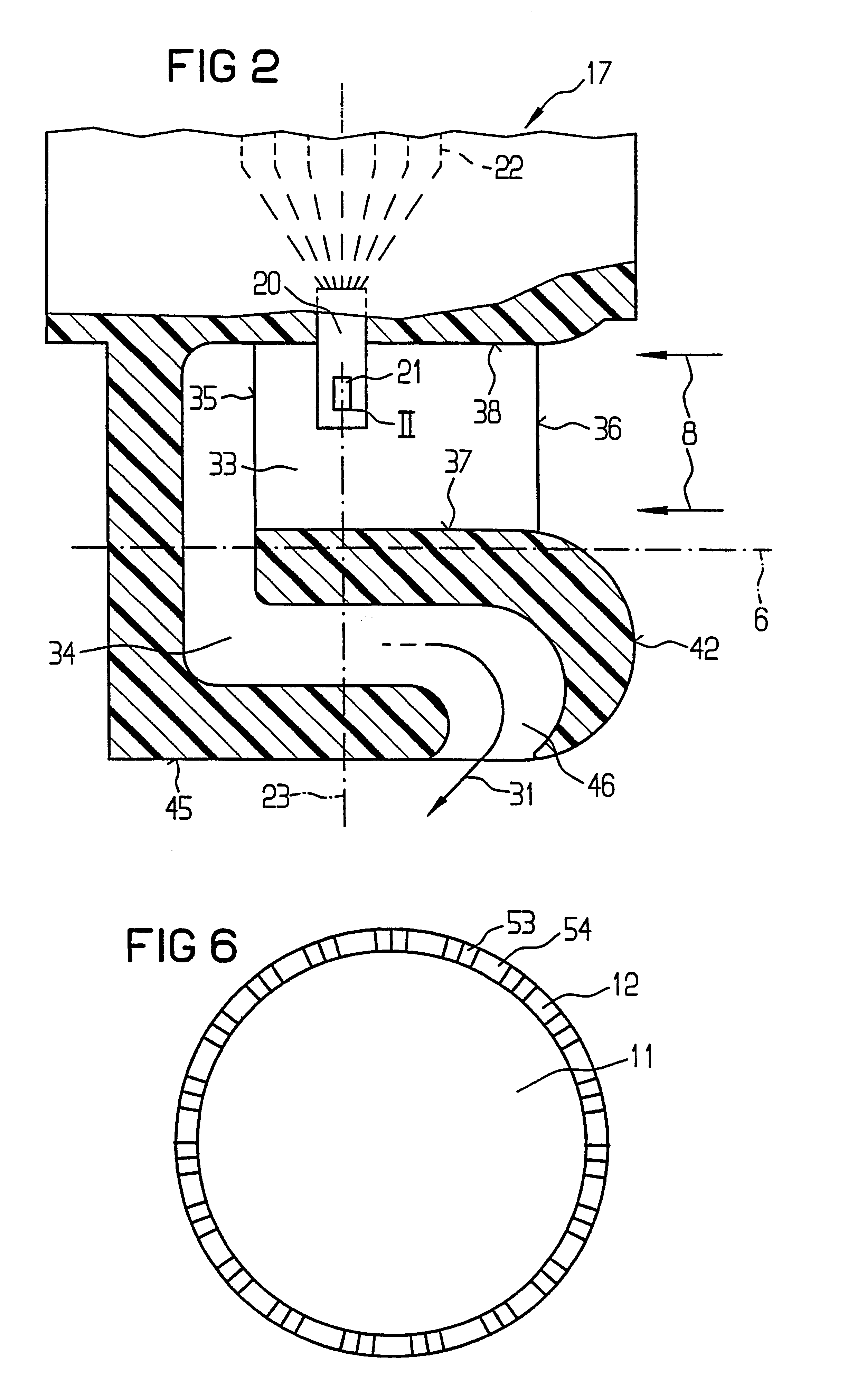
The device according to the invention for measuring the mass of a medium flowing in a line, has the advantage that in operation no irritating whistling noises occur, or at least the whistling is noises are markedly reduced. The structural grooves according to the invention on the outlet end face surrounding the outlet opening prevent eddies in the region of the outlet opening of the flow tube from detaching, which would cause loud, irritating noises. It has been found that the structural grooves of the invention on the outlet end face surrounding the outlet opening do not lessen the above-described fluidic advantages of the flow tube that improve the accuracy of measurement.Advantageous refinements of and improvements to the device defined herein are possible with the provisions recited hereinafter.It has been demonstrated that by means of structural grooves of rectangular, triangular or trapezoidal cross-sectional profile, an especially effective reduction in irritating noises can be attained. Especially preferably, the structural grooves extend radially to the longitudinal axis of the flow tube and are disposed at equal angular intervals on the outlet end face. As a result, a uniform segmentation of the outlet end face is attained, which is advantageous for suppressing the irritating noises. The inlet end face surrounding the inlet opening of the float tube is preferably unstructured, in order not to increase the flow resistance in the region of the inlet opening.Exemplary embodiments of the invention are shown in simplified form in the drawings and described in further detail in the ensuing description. Shown are:FIG. 1, a side view of a first exemplary embodiment of the device according to the invention, in a sectional view;FIG. 2, an enlarged side view, partly in section, of a measurement module used in the exemplary embodiment shown in FIG. 1 of the device of the invention;FIG. 3, a view of the end region of the flow tube, used in the exemplary embodiment of FIG. 1, in the direction marked III in FIG. 1;FIG. 4, a view corresponding to FIG. 3 of a second, modified exemplary embodiment;FIG. 5, a view corresponding to FIG. 3 of a third, modified exemplary embodiment; andFIG. 6, a view of the flow tube, used in the exemplary embodiment shown in FIG. 1, seen in the direction marked VI in FIG. 1, but in which the structural grooves are embodied as shown in FIG. 4.

Problems solved by technology

On the one hand, this limits the engineering and design possibilities and possibilities for installing device considerably, and on the other, the embodiment of the device requires a large installation space.
A disadvantage, however, is that in practical operation a loud, irritating whistling noise occurs.

Method used


Image

  • Device for measuring the mass of a flowing medium
  • Device for measuring the mass of a flowing medium
  • Device for measuring the mass of a flowing medium

Examples


Embodiment Construction

The device 1 shown in section in FIG. 1, serves to measure the mass of a medium flowing in a line 2, in particular the aspirated air mass of an internal combustion engine.

The device 1 can be built in as a mountable adapter element, for instance by means of mounting flanges not shown but provided on the ends, into an intake line through which the engine aspirates air from the environment through an air filter, not shown; via a throttle valve neck, not shown, that is provided for controlling the aspirated air mass, the air reaches a combustion chamber of the engine. The device 1 includes a flow tube 3, which is installed approximately centrally in the line 2 and is mounted on the inner wall 5 of the line 2 by means of spacers 4, shown only schematically. A plurality of spacers 4 may be provided, for instant angles of 120.degree. or 900.degree. from one another. In the exemplary embodiment shown, the flow tube 3 is cylindrical and extends about a longitudinal axis 6, which coincides wi...


PUM


Abstract

A device for measuring the mass of a medium flowing in a line, especially the aspirated air mass on an internal combustion engine, comprising a flow tube, which is disposed in the line. A measuring element around which the flowing medium flows is disposed in the flow tube. The medium flows from the line into the flow tube at an inlet opening and out of the flow tube into the line at an outlet opening. An outlet end face of the flow tube surrounding the outlet opening has structural grooves, which extend with a radial directional component with respect to a longitudinal axis of the flow tube.

Description

PRIOR ARTThe invention is based on a device for measuring the mass of a flowing medium, also called a flow rate meter.From European Patent Disclosure EP 0 087 621 B1, a device for measuring the mass of a medium flowing in a line, in particular the aspirated air mass of an internal combustion engine is known, in which a measuring element, for instance in the form of a hot wire, is placed in a bypass conduit embodied offset from the main aspiration conduit. The opening and closing of the inlet valves of the various cylinders of the engine cause considerable fluctuation or pulsation in the flow velocity in the bypass conduit, and the intensity of this fluctuation or pulsation depends on the aspiration frequency of the individual pistons, or on the engine rpm. These flow fluctuations adulterate the outcome of measurement, namely the average flow velocity prevailing in the bypass conduit and the aspirated air mass of the engine that can be calculated from the aspirated air, considerably....

Claims


Application Information

Patent Timeline
IPC IPC(8): G01F1/684G01F15/00G01F5/00G10K11/16G10K11/00
CPCG01F1/6842G10K11/161G01F15/00G01F5/00G01F1/684
Inventor TANK, DIETERKONZELMANN, UWE
Owner ROBERT BOSCH GMBH
Learn More