Temperature dependent regenerative brake system for electric vehicle

Inactive Publication Date: 2001-08-14
FORD GLOBAL TECH LLC +1
View PDF8 Cites 49 Cited by
  • Summary
  • Abstract
  • Description
  • Claims
  • Application Information

AI Technical Summary

Problems solved by technology

To a vehicle provided with an anti-lock braking system, this rapid acceleration appears as excessive wheel slip.
The anti-lock braking system is thus placed in control of the braking event, which leads to an unnecessa

Method used


Image

  • Temperature dependent regenerative brake system for electric vehicle
  • Temperature dependent regenerative brake system for electric vehicle
  • Temperature dependent regenerative brake system for electric vehicle

Examples


Embodiment Construction

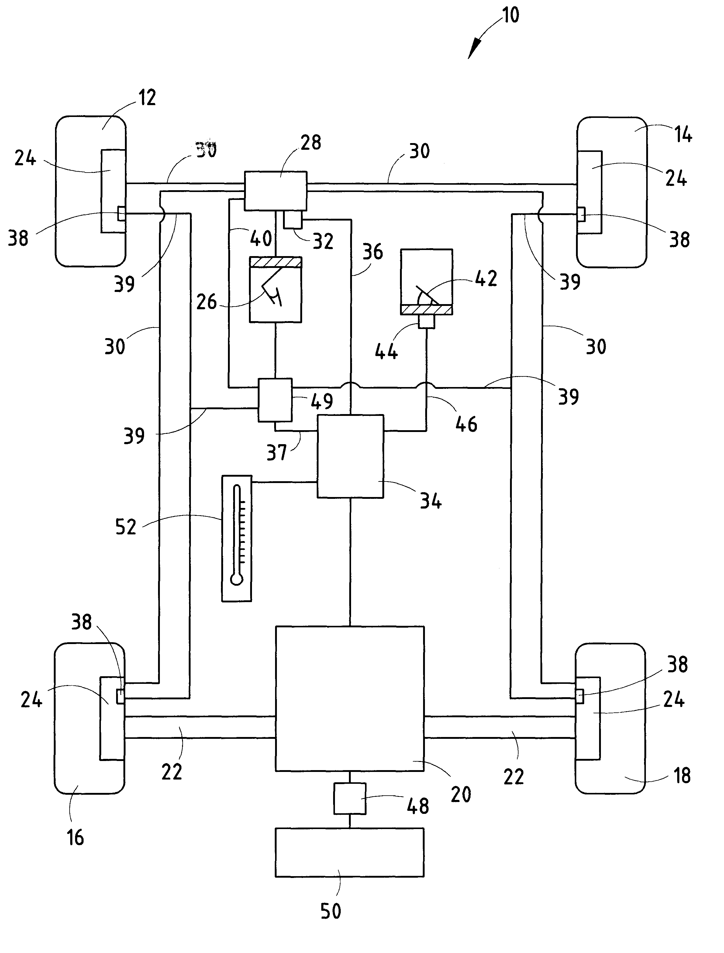
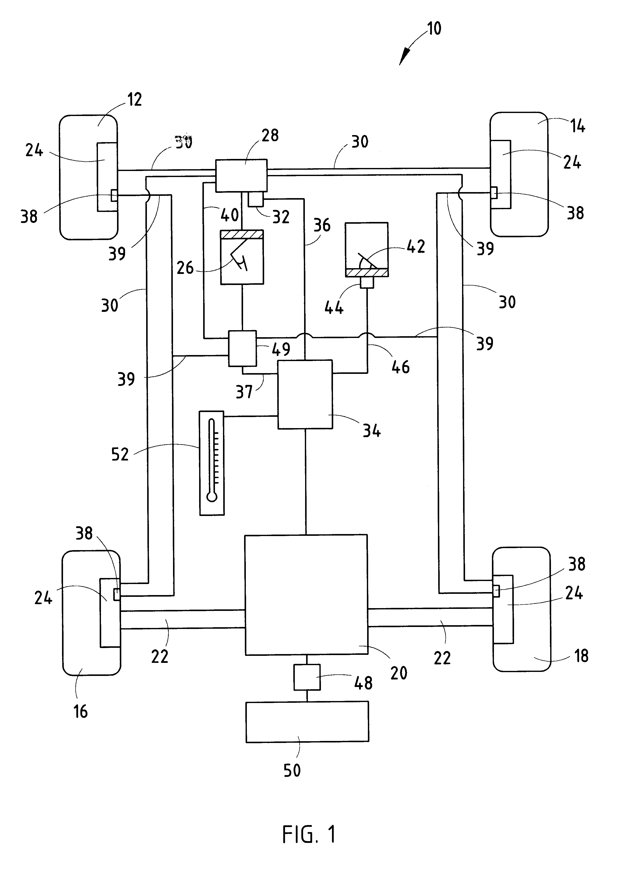
The best mode for carrying out the invention is presented in terms of the preferred embodiment wherein similar reference characters designate corresponding features throughout the figures of the drawings. Referring now to the drawings, particularly FIG. 1, there is shown a motor vehicle 10 having a plurality of wheels 12, 14, 16 and 18 for operation upon a road surface. It should be understood that the term road surface as used herein includes any surface upon which the vehicle 10 may be adapted to operate. An electric motor 20 is provided as the drive motor for driving the rear wheels 16 and 18 through drive shafts 22. While the preferred embodiment utilizes electric motor 20 only as the drive motor, it is contemplated, as being within the scope of the present invention, to further incorporate an internal combustion engine into the vehicle, such as typically found in hybrid vehicles.

Each of the wheels 12, 14, 16, 18 are further preferably provided with a conventional friction brake...


PUM


Abstract

A braking system for a motor vehicle having braking wheels 16, 18, a service brake pedal, a friction braking system operative upon the braking wheels 16, 18 in response to actuation of the vehicle brake pedal 26, an anti-lock braking system cooperative with the friction braking system to control the friction braking force applied to the braking wheels 16, 18 upon detection of slippage of the braking wheels 16, 18, a regenerative braking system operative upon the braking wheels 16, 18 in response to actuation of the vehicle brake pedal 26 for selectively generating an applied regenerative braking force through the braking wheels 16, 18, and an ambient temperature sensor 52. The regenerative braking system operates at a first effective rate of applied regenerative braking force upon application of the brake pedal 26 at an ambient temperature above a desired temperature, and the regenerative braking system operates at a second, lower effective rate of applied regenerative braking force at an ambient temperature below a desired temperature. Upon activation of the anti-lock braking system, the applied regenerative braking force is reduced at a first predetermined rate when the ambient temperature is above a desired temperature and the regenerative braking force is reduced at a second, faster predetermined rate when the ambient temperature is below a desired temperature.

Description

This invention relates to a regenerative braking system for a motor vehicle used to recapture vehicle kinetic energy during a braking event. More particularly, the present invention relates to a control strategy for a vehicle equipped with both a regenerative braking system and an anti-lock brake system for selectively controlling the regenerative braking effort provided by the regenerative braking system.DESCRIPTION OF THE RELATED ARTElectric motor vehicles typically incorporate regenerative braking, delivered to the drive wheels by the electric motor, to supplement the friction brake system and to recover a portion of the vehicle's kinetic energy during the braking event to increase vehicle range. Regenerative braking may be applied whenever the driver deactivates the accelerator pedal, sometimes referred to as compression regeneration, and is applied more aggressively when the driver presses the brake pedal, commonly referred to as service brake regeneration.It is also common in ...

Claims


Application Information

Patent Timeline
IPC IPC(8): B60L7/26B60L7/00B60T1/00B60T1/10B60T13/74B60T13/00B60T8/00
CPCB60L7/26B60T1/10B60T13/748B60T8/00Y10S188/01B60T2270/602
Inventor LOTITO, DAVID JAMESSAGAN, CLEMENT NEWMANXU, JACK H.
Owner FORD GLOBAL TECH LLC
Why Eureka
Try Eureka