Centrifuge chamber for a cell separator having a spiral separation chamber

a cell separator and centrifuge chamber technology, which is applied in centrifuges, centrifugal force sediment separation, withdrawing sample devices, etc., can solve the problems of unclean or inadequate separation of platelets in one-step separation chambers, and the inside and outside walls of separation channels may not form a steady path

Inactive Publication Date: 2001-08-21
FRESENIUS AG
View PDF24 Cites 99 Cited by
  • Summary
  • Abstract
  • Description
  • Claims
  • Application Information

AI Technical Summary

Problems solved by technology

Centrifuge chambers with a multi-step separation channel have the disadvantage that cells which have already been separated may be entrained into another fraction by turbulent eddies in the transition area between the individual sections of the channel.
Thus, for example, there is the risk that platelets which have already been separated m

Method used


Image

  • Centrifuge chamber for a cell separator having a spiral separation chamber
  • Centrifuge chamber for a cell separator having a spiral separation chamber
  • Centrifuge chamber for a cell separator having a spiral separation chamber

Examples


Embodiment Construction

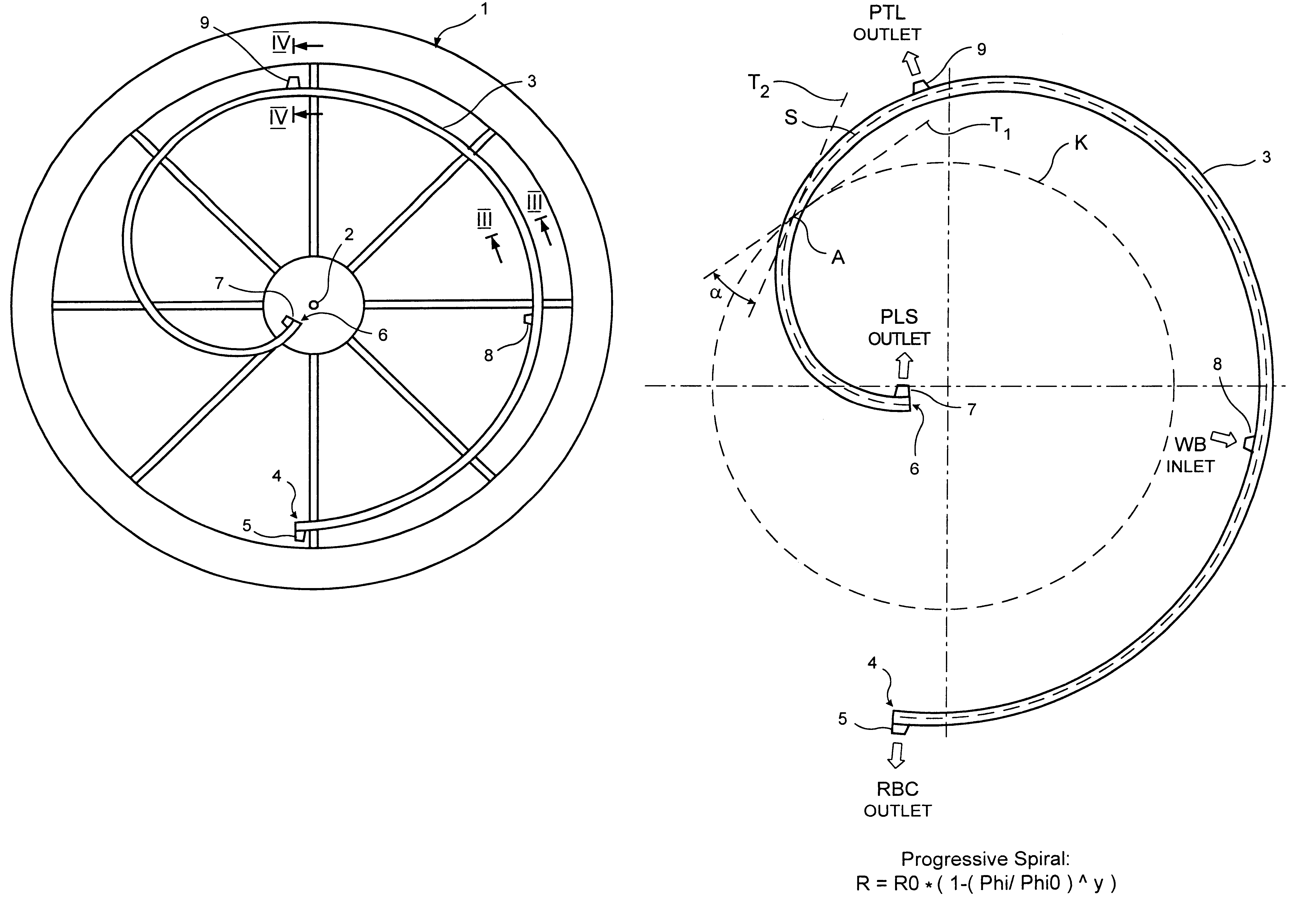
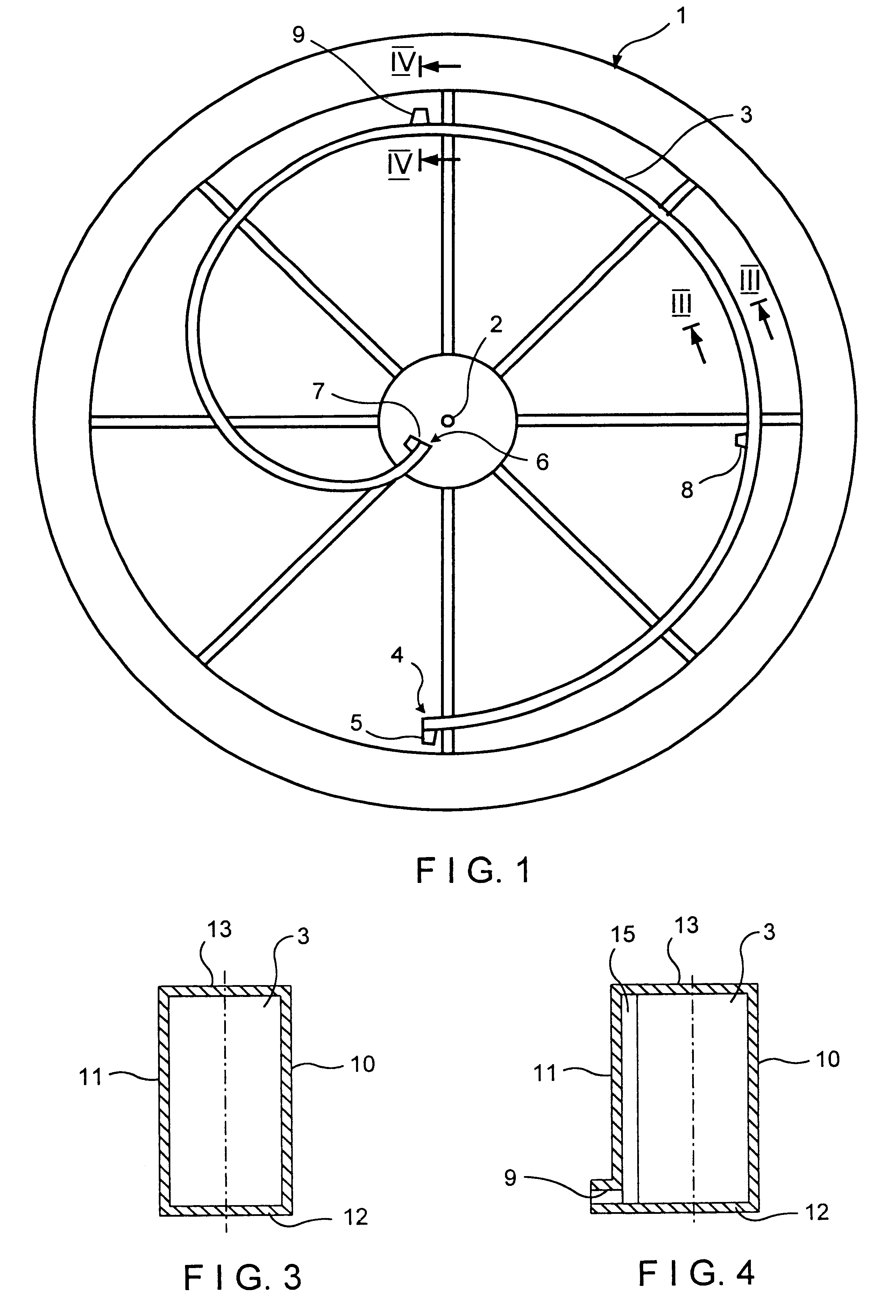
One embodiment according to the invention is described with reference to FIGS. 1 to 4. The centrifuge chamber has a circular housing body 1 which can be inserted into a cell separator. Housing body 1 rotates about a vertical axis of rotation 2 in the cell separator. Housing body 1 has a separation channel 3 which extends around axis of rotation 2 of the centrifuge chamber.

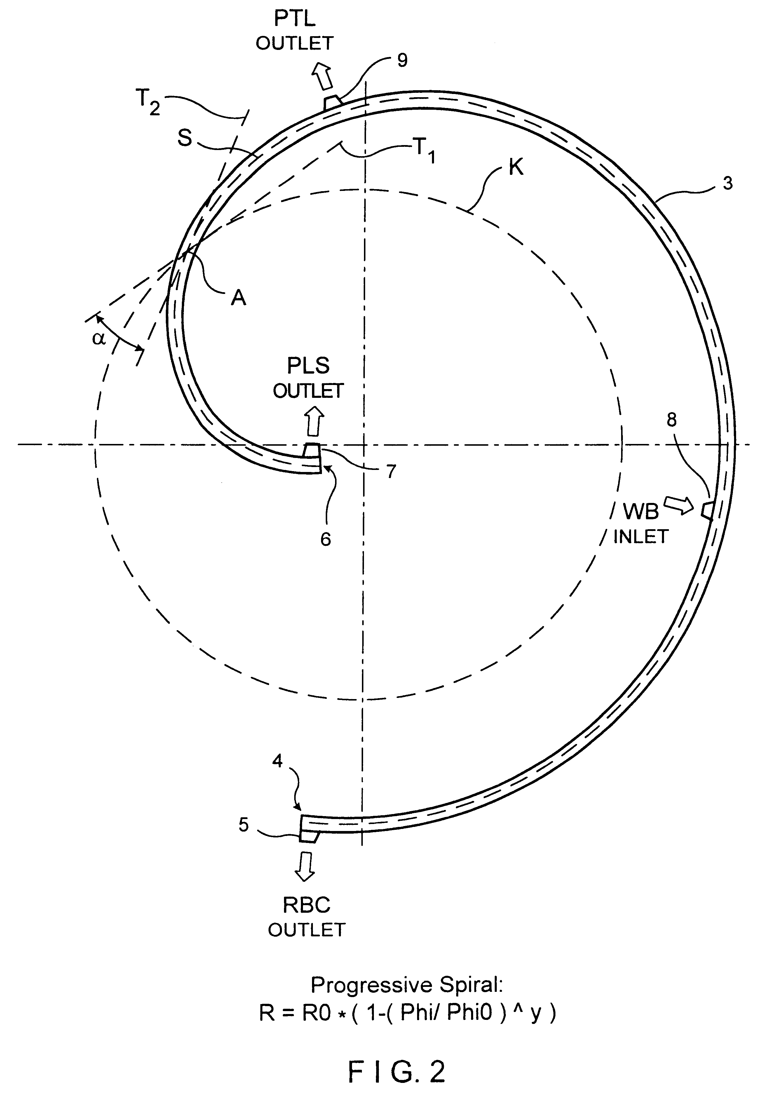
At its outer end 4, the separation channel 3 has a first outlet 5 for erythrocytes (RBC). A second outlet 7 for plasma (PLS) is located at the inner end 6 of separation channel 3. Between erythrocyte outlet 5 and plasma outlet 7, separation channel 3 has an inlet 8 for inserting the whole blood (WB) to be separated. A third outlet 9 for platelets (PLT) is arranged between whole blood inlet 8 and plasma outlet 7. The inlet and outlets are preferably distributed at essentially uniform intervals over the length of the channel.

The path of separation channel 3 and the arrangement of the inlet and outlet connections for ...


PUM

PropertyMeasurementUnit
Angleaaaaaaaaaa
Fractionaaaaaaaaaa
Heightaaaaaaaaaa

Abstract

A centrifuge chamber of a cell separator having a separation channel with an inlet to introduce the cell suspension and at least one outlet to withdraw a fraction of the cell suspension is described. The cell suspension can be blood. The separation channel is shaped like a spiral extending from the radially outer end of the channel to the radially inner end of the channel, with a progressive slope. The centrifuge chamber allows a uniform, contaminant free separation of the cell suspension into its components.

Description

This invention relates to a centrifuge chamber for a cell separator, in particular for separating blood into several fractions.DESCRIPTION OF THE RELATED ARTCell separators having a centrifuge chamber are used for separating whole blood into its individual components.The centrifuge chamber of known cell separators has a separation channel into which the cell suspension to be separated is sent. Under the influence of centrifugal force, the blood is separated in the separation channel into different fractions, such as platelets (PLT), erythrocytes (RBC), platelet-rich plasma (PRP) and platelet-poor plasma (PPP) which are discharged from the chamber.The centrifuge chamber of known cell separators for separating blood into multiple fractions is generally intended for a single use. One-part and two-part centrifuge chambers are also known. In two-part centrifuge chambers, the separation channel is formed by a flexible film part inserted into a rigid receptacle unit. The separation channel...

Claims


Application Information

Patent Timeline
IPC IPC(8): B04B5/04B04B5/00A61M1/02G01N1/10G01N33/48
CPCB04B5/0442B04B2005/045
Inventor NEUMANN, HANS-JURGEN
Owner FRESENIUS AG
Why Eureka
Try Eureka