
UV sensor

a technology of ultraviolet light and sensor, applied in the field of ultraviolet light sensors, can solve the problems of changing the reading produced, aperture passing the rays with unattenuated intensity, and long-standing problems

Inactive Publication Date: 2001-08-21
ELECTRONICS INSTR & TECH INC
View PDF2 Cites 14 Cited by
  • Summary
  • Abstract
  • Description
  • Claims
  • Application Information

AI Technical Summary

Problems solved by technology

Solarization presents a major problem in UV measuring instruments because it changes the transmission characteristics of the measurement light path and hence, changes the reading produced by the instrument.
However, UV measurements require a finite number of photons striking a unit area to make a measurement.
The problem is a long standing problem.
However, if the light rays are collimated (parallel to each other), the aperture will pass the rays with unattenuated intensity.
Thus, the Hayes et al. approach works only for large area sources.

Method used


Image

  • UV sensor
  • UV sensor
  • UV sensor

Examples


Embodiment Construction

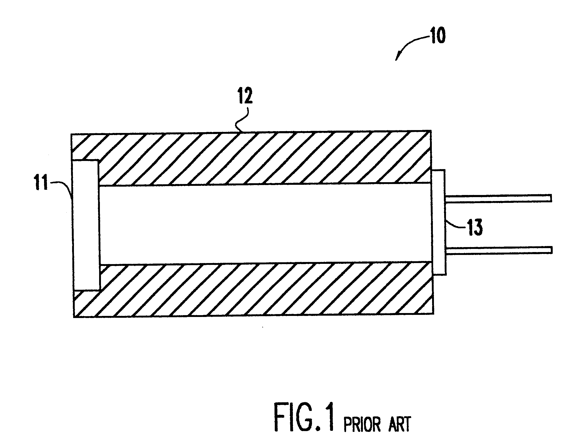
Referring now to the drawings, and more particularly to FIG. 1, there is shown a representation of a typical UV sensor 10. UV light is passed through an optical filter 11 which rejects all wavelengths except those of interest. The filter 11 is contained within and at one end of a housing 12. At the other end of the housing 12 is a silicon photodetector 13, whose output is a current proportional to the number of photons striking it per unit time (intensity), which is the sensing element. While not part of this invention, the current from the sensor is converted to a voltage by an external circuit (not shown) and intensity is read as a numerical value on a voltage reading device (also not shown).

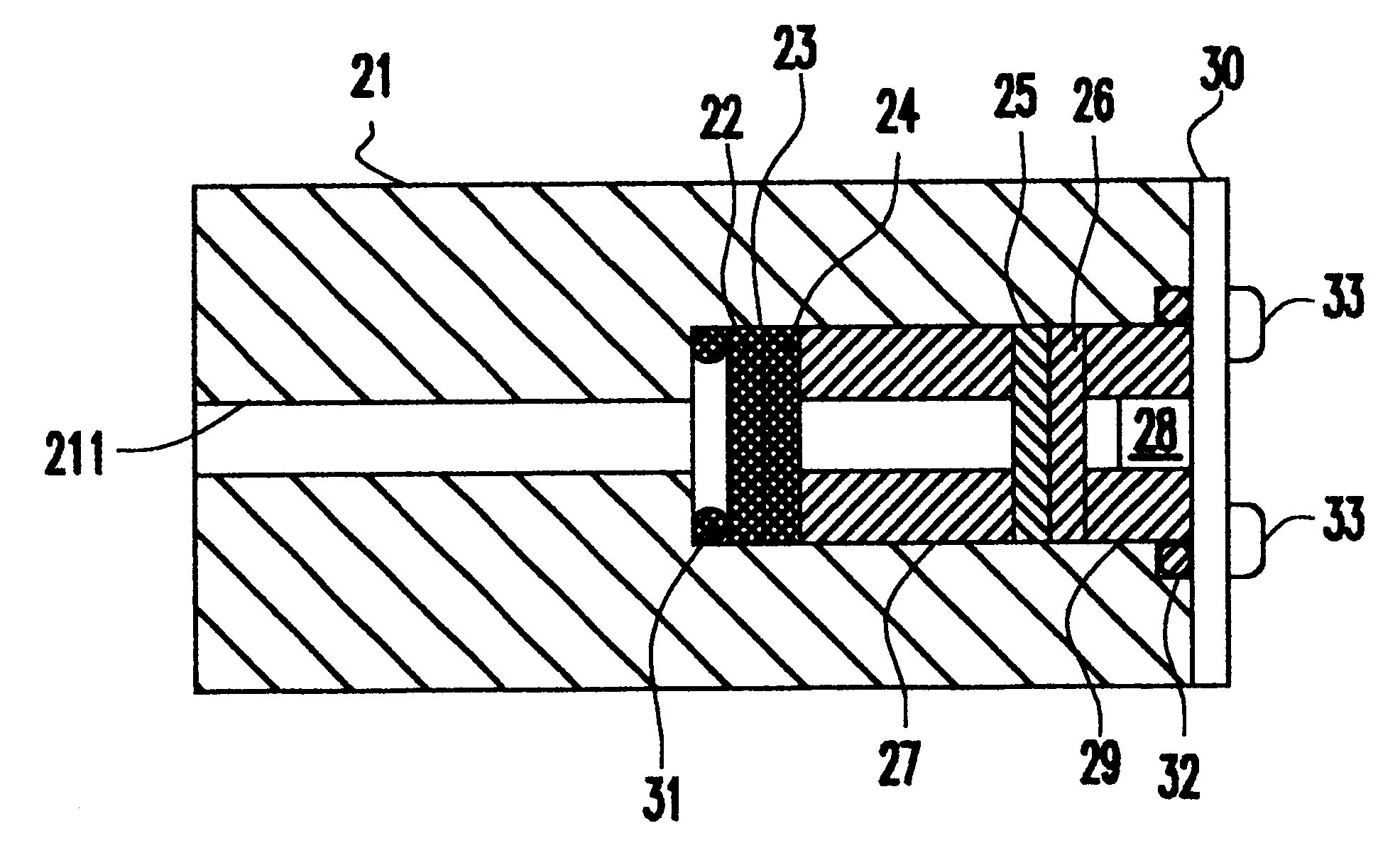
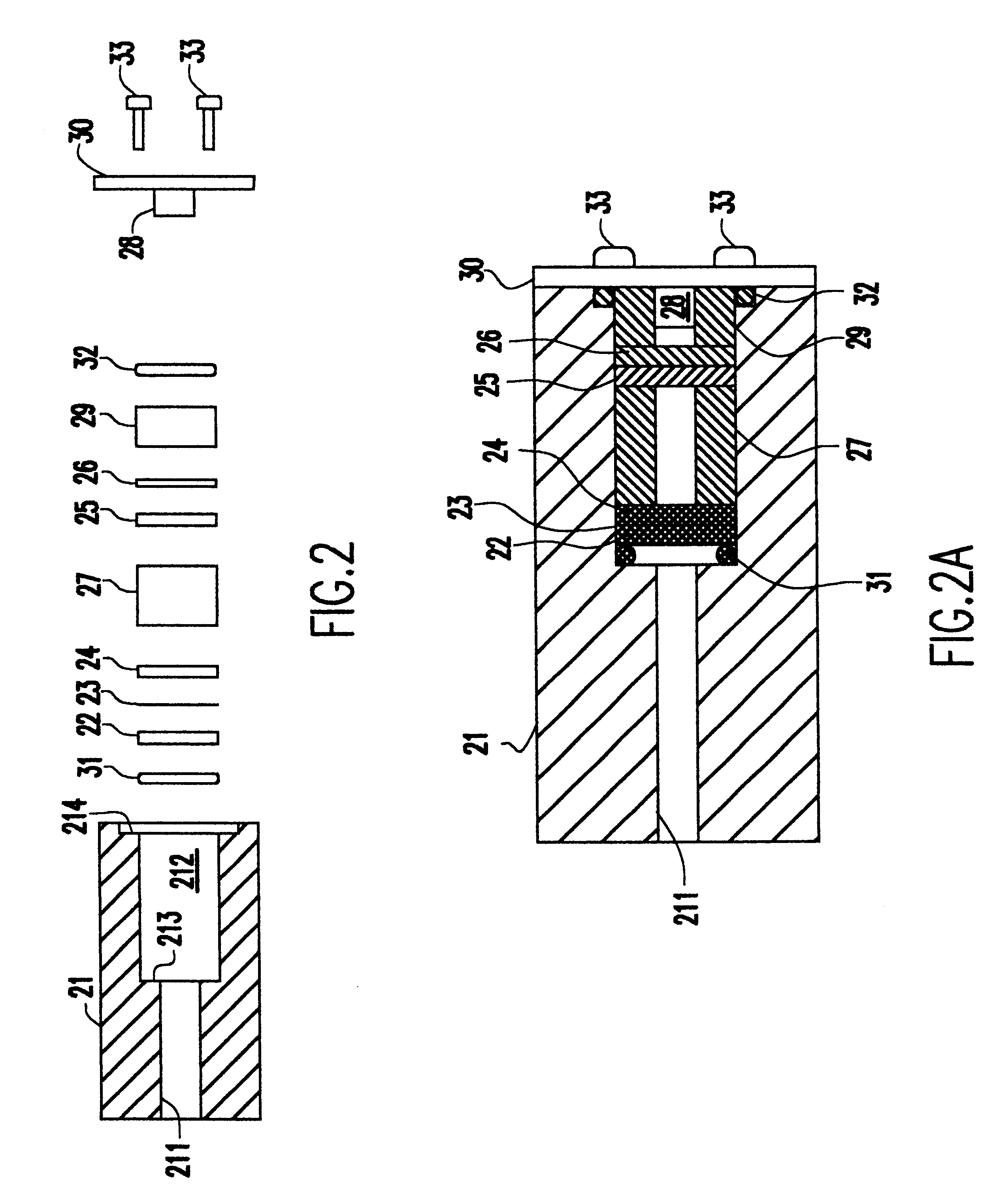
A typical very low solarization sensor design is shown in exploded cross-section in FIG. 2 and assembled in FIG. 2A. An aluminum housing 21, which contains the optical components, is mechanically oriented so that its viewing port 211 opening at one end of the housing is exposed to a UV source....


PUM


Abstract

A UV sensor design which virtually eliminates solarization effects on optical components and photodetector and is effective for both broad area and collimated light sources. The sensor design reduces the number of photons striking a unit area of any of the materials in the light path sensitive to UV light to a level which does not produce appreciable solarization over very long periods of time. The UV sensor has as the first optical element in the viewing path a UV transmitting, extremely low solarization window. The back surface of this window is frosted to produce some diffusion of the UV rays. A small metal disc with a very small aperture is the next optical element and reduces the total amount of energy admitted to the optical measurement system. A second frosted UV transmitting, extremely low solarization window further diffuses the light beam passing through the aperture. The UV light from this second window travels toward to two UV filters and is further dispersed to produce low intensity level UV light which impinges on a silicon photodetector.

Description

1. Field of the InventionThe present invention generally relates to ultraviolet sensors and, more particularly, to a sensor design which virtually eliminates solarization effects on optical components and photodetector.2. Background DescriptionUltraviolet (UV) radiation has been long known to produce solarization in materials. Solarization presents a major problem in UV measuring instruments because it changes the transmission characteristics of the measurement light path and hence, changes the reading produced by the instrument.The degree of solarization is a function of, among other factors, how many UV photons strike the material. Since there is a finite probability that a single photon striking a piece of material will cause a physical change in the material, one key to reducing solarization is to reduce the number of photons striking the material in question. However, UV measurements require a finite number of photons striking a unit area to make a measurement.The problem is a ...

Claims


Application Information

Patent Timeline
IPC IPC(8): G01J1/42G01J1/04G01J1/02
CPCG01J1/04G01J1/0437G01J1/429G01J1/0474G01J1/0271G01J2001/0276G01J1/0488
Inventor MAY, JOE T.
Owner ELECTRONICS INSTR & TECH INC
Learn More