
Milling tool with precisely positionable inserts

a technology of inserts and milling tools, which is applied in the field of milling tools, can solve the problems of manual adjustment of the cassette during the assembly of the tool, the inability to achieve a predetermined, precisely defined initial position of the cassette, and the inconvenience of the design of the known tool

Inactive Publication Date: 2001-08-28
SANDVIK INTELLECTUAL PROPERTY AB
View PDF9 Cites 20 Cited by
  • Summary
  • Abstract
  • Description
  • Claims
  • Application Information

AI Technical Summary

Benefits of technology

The present invention aims at obviating above-mentioned inconveniences of the previously known milling tool and at providing an improved milling tool. Therefore, a primary object of the invention is to provide a milling tool in which the machining elements, preferably in the form of cassettes having detachable cutting inserts, can be located in a simple way in an exactly defined operating position in relation to the tool body during the assembly of the tool. In other words, it should be possible to mount the machining elements rapidly without having to finely adjust them manually. Another object is to provide a milling tool with a good ability to resist at least minor incidents, which could cause breakdowns in connection with impacts or shock loads of an instantaneous character, which may occur. In particular, the machining element or should be able to resist such loads without being seriously damaged or displaced from its basic position. Another object of the invention is to provide a milling tool that is suitable for operation at very high rotational speeds, e.g. all the way up to the range of 20,000-30,000 revolutions / minute.

Problems solved by technology

However, this countersink has a larger diameter than the locator pin, so when the cassette is initially installed in the recess, the cassette does not attain a predetermined, exactly defined axial initial position.
The job of finely adjusting the cassette manually during the assembly of the tool is difficult and time-consuming.
Another inconvenience of the design of the known tool is that it has only a limited ability to resist minor breakdowns of the type that easily may arise when the cassettes, together with the cutting inserts, are submitted to instantaneous impacts or shock loads.
Therefore, even if total breakdowns can be avoided, frequently so much damage occurs to the cassettes that the cassettes have to be discarded and replaced.
That means that, in practice, the tolerance chain between, on the one hand, the tool body together with the rotation axis thereof and, on the other hand, each one of the several cutting inserts, becomes extensive.
This entails, among other things, that the precision in the adjustment of the cutting insert in relation to the tool body (which in practice should be less than 1 / 100 mm) may easily be lost or become unsatisfactory, e.g. when the cutting inserts are replaced or indexed or when the cassette, for one reason or another, has to be dismounted and remounted.

Method used


Image

  • Milling tool with precisely positionable inserts
  • Milling tool with precisely positionable inserts
  • Milling tool with precisely positionable inserts

Examples


Embodiment Construction

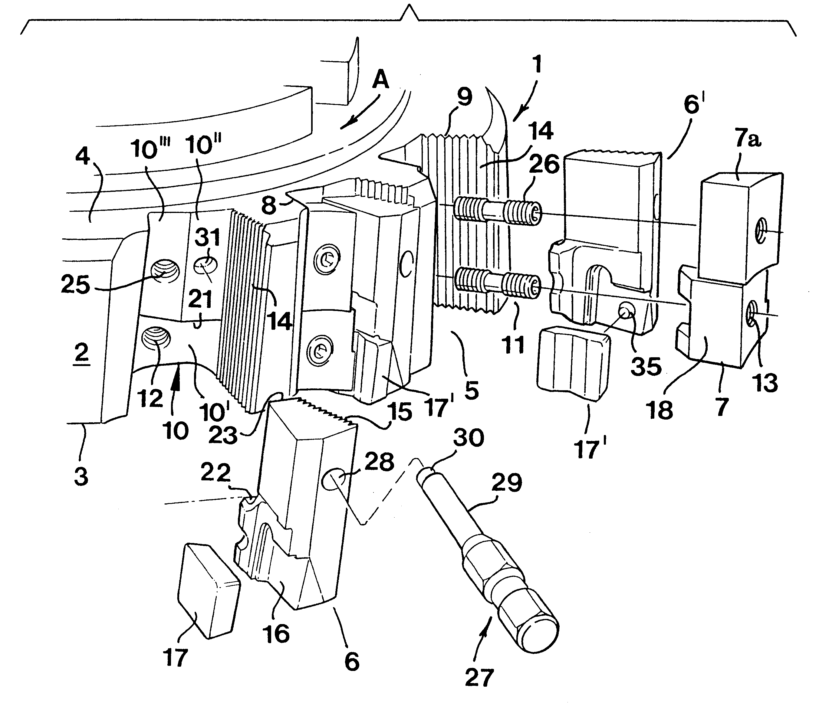
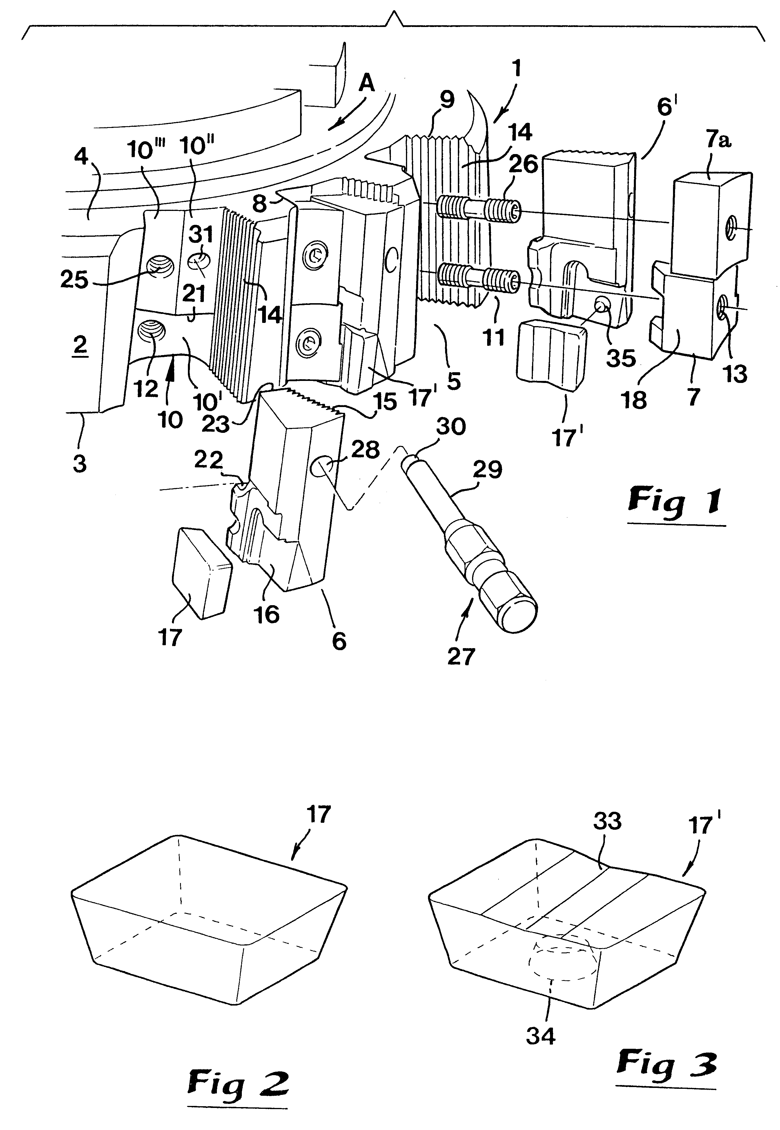
In FIG. 1, there is shown a body 1 in the form of a cutter head which is rotatable around a central geometric longitudinal axis (not shown). In the example, the body 1 is delimited by a peripheral, envelope-like surface 2, which extends between opposite axially spaced end surfaces 3, 4. The first-mentioned side 3 consists of a front side in the vicinity of which a tool cutting insert 17 is located, while the last-mentioned side 4 consists of a rear side to which a rotatable spindle or the like (not shown) is connected in a suitable way.

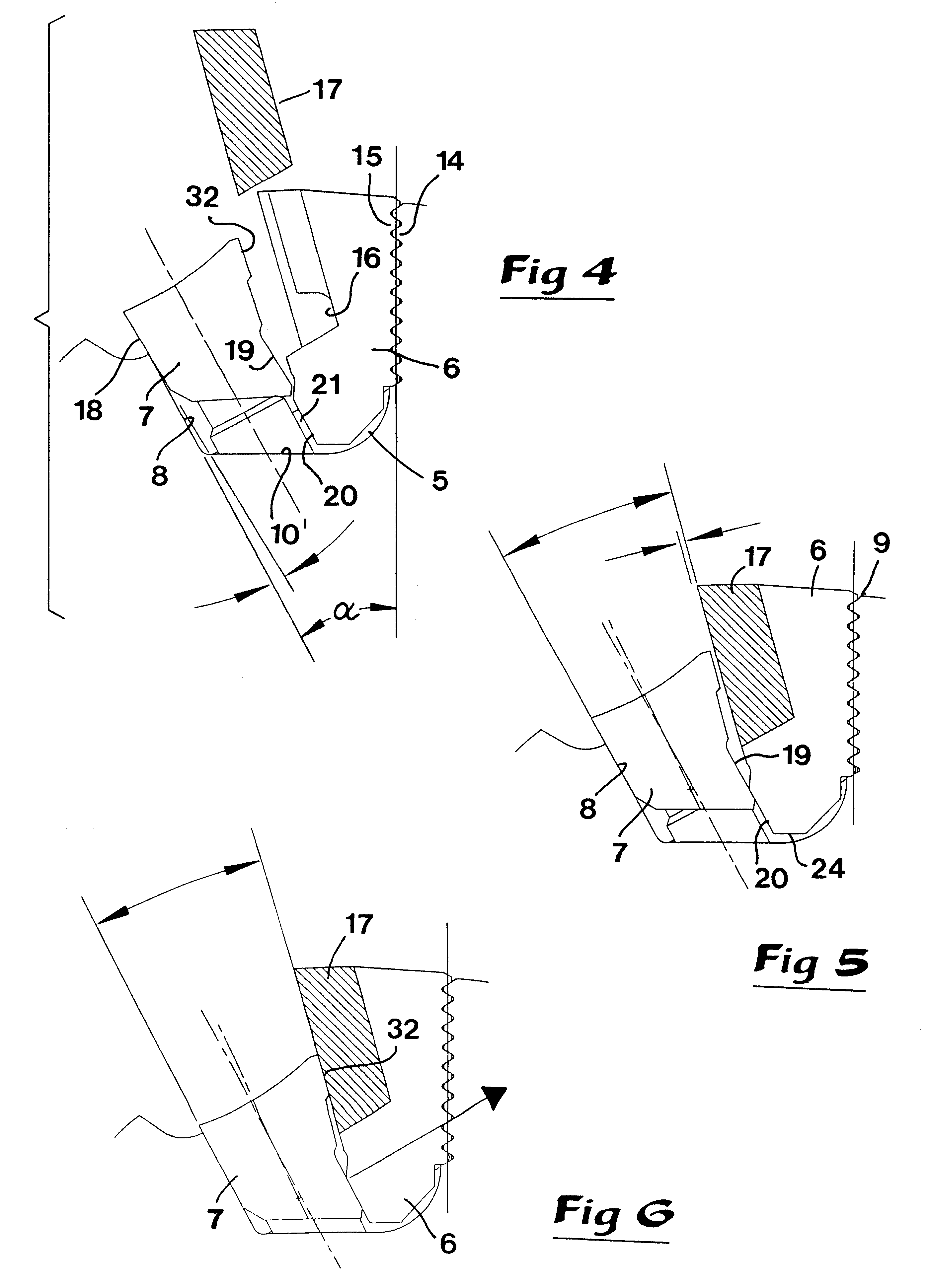
Recesses 5, which open radially outwards, extend longitudinally through the envelope surface 2, the purpose of these recesses being to accommodate machining elements, preferably in the form of cassettes 6 which carry replaceable cutting inserts, as well as at least one clamping wedge 7. Each separate recess 5 (see also FIGS. 4-6) is delimited by a radially extending front wall 8, a radially extending rear wall 9 and a bottom wall 10 interconnecting ra...


PUM


Abstract

A cutter head of a milling tool is equipped with machining elements which can be fastened in respective recesses of a rotary body by one or more clamping wedges. On the rear side of the individual machining element there are serrations which co-operate with serrations formed in a rear wall of the recess. The serrations extend generally parallel to an axis of rotation of the cutter head. A bottom wall in the recess is divided into a plurality of wall parts which are separated by a first axially facing abutment surface against which an axially facing a second abutment surface on the machining element can be engaged, to define an exact initial mounting location for the machining element.

Description

This invention relates to a metal-cutting milling tool.Such tools are known that comprise a body rotatable around a central geometric axis, which body has a peripheral envelope surface extending between opposite end surfaces. In the envelope surface, recesses are provided which open outwards, each recess defined by a front wall, a rear wall and a bottom wall and has the purpose of receiving a machining element (e.g., a cassette which carries a cutting insert) as well as at least one clamping wedge arranged in the recess for fixing the machining element in place. The clamping wedge can be tightened by means of a clamping screw which enters a threaded hole formed in the bottom wall of the recess. The rear wall of the recess has first serrations arranged to co-operate with second serrations disposed on a rear side of the machining element, while the front wall is smooth in order to cooperate with a similar smooth front surface on the clamping wedge. A contact surface on the clamping we...

Claims


Application Information

Patent Timeline
IPC IPC(8): B23C5/20B23C5/24B23C5/16B23C5/22
CPCB23C5/207B23C5/2226B23C5/2278B23C5/2479Y10T407/1938Y10T407/1912Y10T407/1932Y10T407/1944B23C5/202B23C5/00
Inventor QVARTH, INGEMAR
Owner SANDVIK INTELLECTUAL PROPERTY AB
Learn More