
Borehole caliper derived from neutron porosity measurements

Inactive Publication Date: 2001-09-04
SCHLUMBERGER TECH CORP
View PDF13 Cites 34 Cited by
  • Summary
  • Abstract
  • Description
  • Claims
  • Application Information

AI Technical Summary

Problems solved by technology

The algorithm is relatively complex, and the range of borehole diameter variation over which reliable compensation can be obtained is relatively limited.
Although yielding a more representative measure of borehole size than a single arm device, multiple-arm devices are notoriously complex mechanically, difficult to operate effectively in harsh borehole conditions, difficult to maintain calibrated, and expensive to fabricate.
Prior art LWD systems, like their wireline counterparts, are sensitive to borehole size.
It is readily apparent that arm type wireline calipers are not applicable to LWD since the drill string is typically rotating, and the arms engaging the penetrated formation would be quickly severed by this rotational movement.
Again, generally speaking, this method of calipering a borehole and correcting measurements for borehole effects is not reliable.
In addition, a relatively complex suite of LWD devices must be employed in order to practice this method.
These required features greatly increase the complexity of the borehole instrument, increase the demands on the logging-while-drilling telemetry system, and necessitate a relatively complex interpretation algorithm.
The acoustic caliper methodology requires an additional LWD system which is relatively complex and which must operate in the harsh drilling environment.
This decreases reliability, increases operational cost, and increases the manufacturing cost of the LWD assembly.
Furthermore, any type of reliable acoustic measurement is difficult to obtain in the acoustically "noisy" drilling environment.
This ratio method does not, however, provide complete borehole size compensation.
Although porosity measurements produced by the Evans system require no caliper for correcting porosity measurements for borehole size, the system disclosed no means for generating a caliper log from the response of the tool.

Method used


Image

  • Borehole caliper derived from neutron porosity measurements
  • Borehole caliper derived from neutron porosity measurements
  • Borehole caliper derived from neutron porosity measurements

Examples


Embodiment Construction

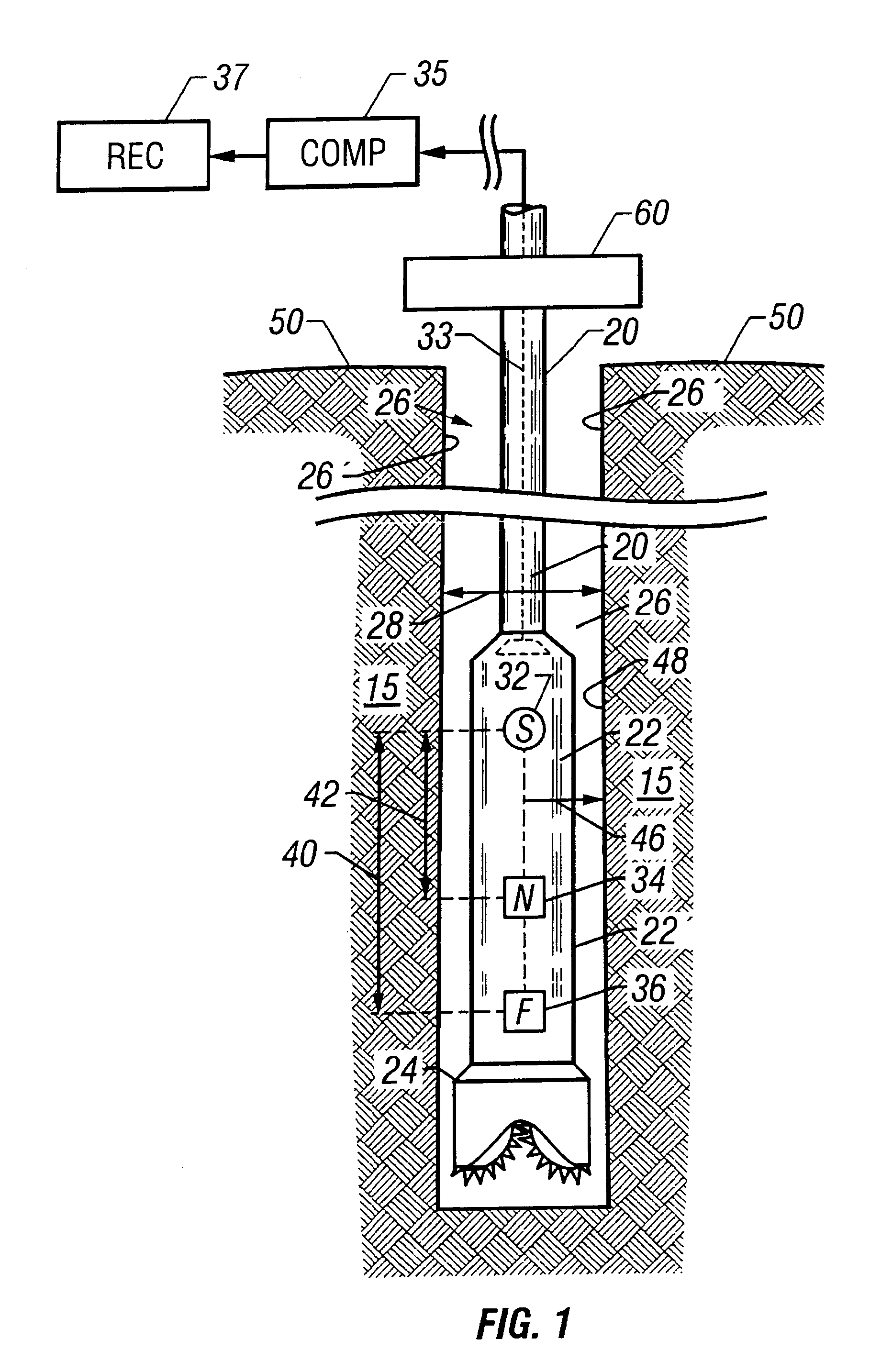
FIG. 4 illustrates a borehole caliper system configured as a dual detector neutron porosity device embodied for wireline operations. A neutron source 116 is preferably axially aligned with a near detector 114 and a far detector 112 within a pressure tight, cylindrical instrument or sonde 110. The upper end of the sonde 110 is suspended from a sheave wheel 132 by means of a wireline 102 within a borehole 100 of diameter 104 which penetrates a formation 101. The near detector 114 is spaced a distance 122 preferably above the source 116, and the far detector 112 is spaced a distance 120 preferably above the source 116. As in the LWD embodiment of the system, the axial positions of the detectors with respect to the source can be reversed, and the near detector and the far detector can alternately be axially positioned on either side of the source, respectively. Count rate data C.sub.near from the near detector 114 is preferentially responsive to borehole fluid within the annulus defined...


PUM


Abstract

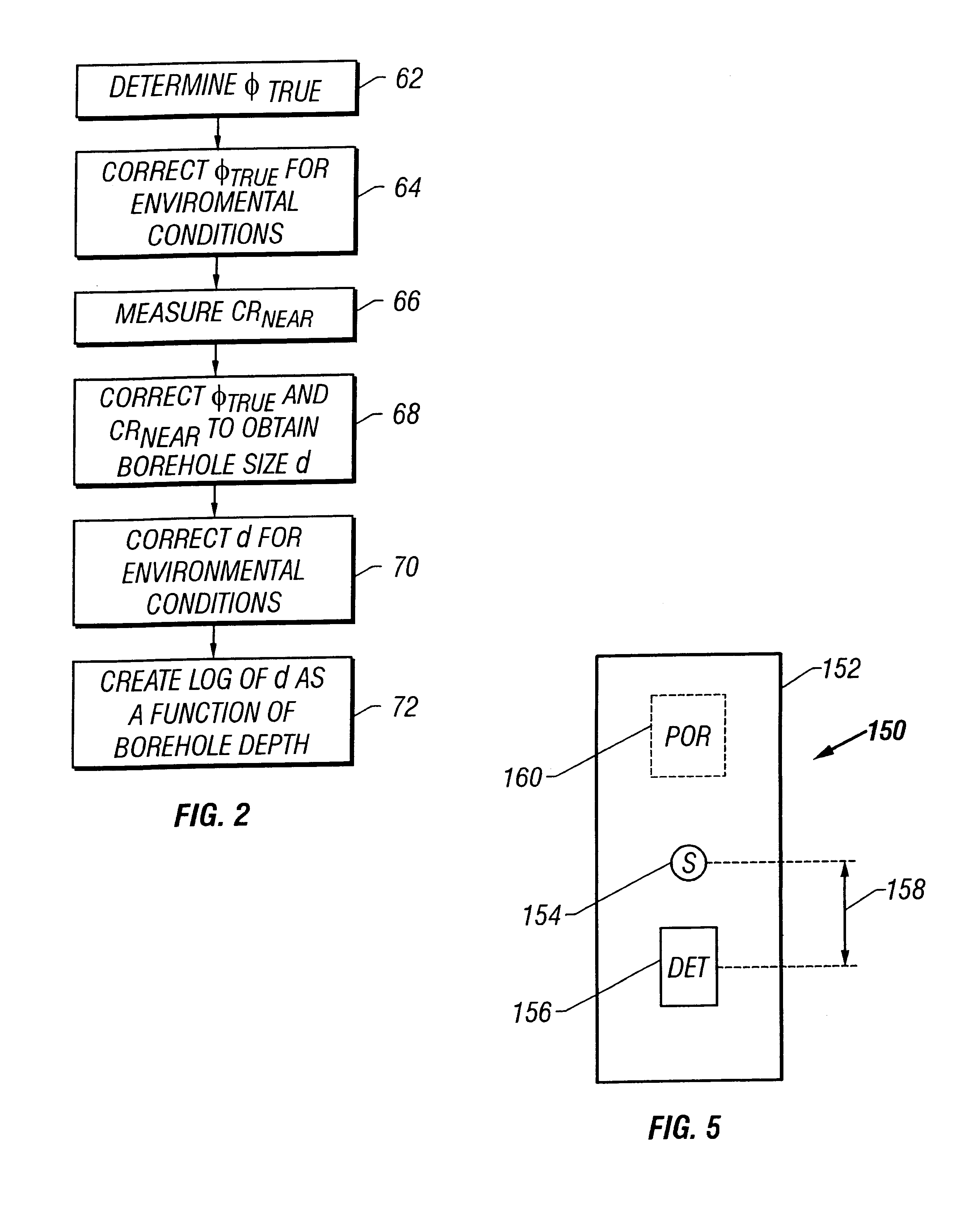
A system for measuring the size of a borehole penetrating an earth formation is disclosed. The system uses a neutron source and a least one neutron detector. The neutron detector responds primarily to the composite hydrogen content of material within the borehole and formation upon irradiation by the neutron source. A partition response function is used to delineate the portion of the detector response resulting from borehole and from the formation. Since the detector response from the borehole can be isolated using the partition function and the hydrogen content of the borehole fluid is generally known, the size of the borehole can be determined from borehole response portion of the composite detector response if combined with a neutron porosity measurement of the formation. The neutron porosity measurement can be obtained independently, or by combining the neutron detector response with the response of a second neutron detector at a different axial spacing from the neutron source. The system is applicable in both logging-while-drilling and wireline logging operations.

Description

1. Field of the InventionThis invention is directed toward the determination of radial dimensions or "caliper" of a borehole penetrating earth formation, and more particularly directed toward determining caliper by irradiating formation with neutrons and measuring neutron flux within the borehole. The invention can be embodied to measure caliper while the borehole is being drilled, or alternately embodied to measure caliper as a wireline logging system used after borehole drilling has been completed.2. Description of the ArtAccurate borehole caliper data is important for both the drilling of a well borehole, in the measurement of earth formation parameters penetrated by the borehole, and in completing the well after drilling.In drilling a typical borehole for hydrocarbon production, the drill string is formed from sections or "joints" of drill pipe which are added to the drill string by threaded collars, and which is terminated by a drill bit. The drill string is rotated my means we...

Claims


Application Information

Patent Timeline
IPC IPC(8): E21B47/00E21B47/08
CPCE21B47/082E21B47/085
Inventor EVANS, MICHAEL L.BEST, DAVID L.
Owner SCHLUMBERGER TECH CORP
Learn More