RCC power supply with remote disabling of oscillation frequency control

a power supply and frequency control technology, applied in the direction of electric variable regulation, process and machine control, instruments, etc., can solve the problems of increasing the frequency of occurrence of switching loss per unit time, and reducing the reduction of load

Inactive Publication Date: 2001-09-04
MURATA MFG CO LTD
View PDF12 Cites 27 Cited by
  • Summary
  • Abstract
  • Description
  • Claims
  • Application Information

AI Technical Summary

Problems solved by technology

In general, the switching loss which occurs during each switching operation decreases with the reduction in the load.
However, since the oscillation frequency f increases, as shown in FIG. 10, with the reduction in the output power Po and thus with the reduction in the load, the frequency of occurrence of switching loss per unit time increases with the increase in the oscillation frequency f. Therefore, the reduction in the switching loss which occurs when the load decreases is very small.
If the oscillation frequency is set to a too low value, problems such as saturation of the transformer occur.
Therefore, the rectifying and smoothing circuit causes an increase in the oscillation frequency.
However, if the switching frequency is reduced to a too low value in the audio-frequency range, the switching operation can cause audible noise.
However, the increase in the current from the starting circuit results in an increase in the power loss due to the starting circuit because the current from the starting circuit always flows regardless of whether the apparatus is in the waiting state or not.

Method used


Image

  • RCC power supply with remote disabling of oscillation frequency control
  • RCC power supply with remote disabling of oscillation frequency control
  • RCC power supply with remote disabling of oscillation frequency control

Examples


Embodiment Construction

Hereinafter, the preferred embodiments of the present invention are explained in detail with reference to the drawings.

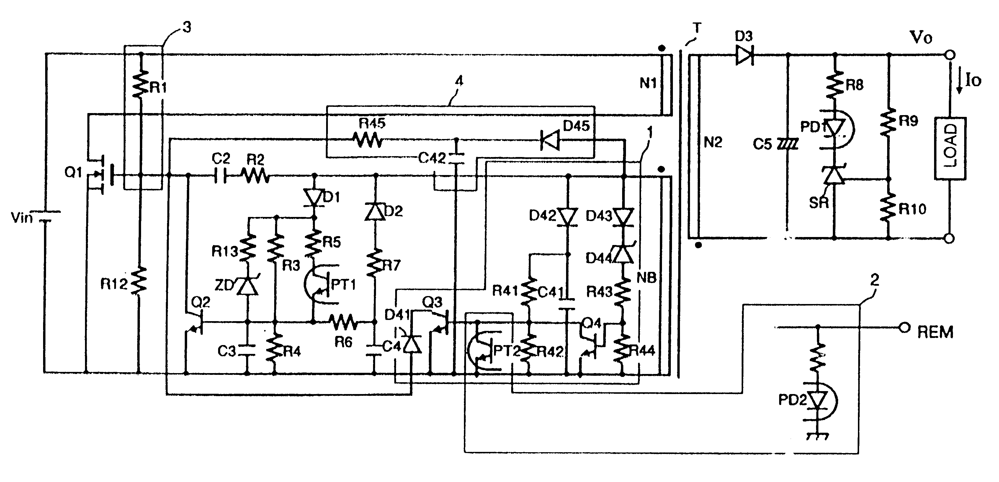
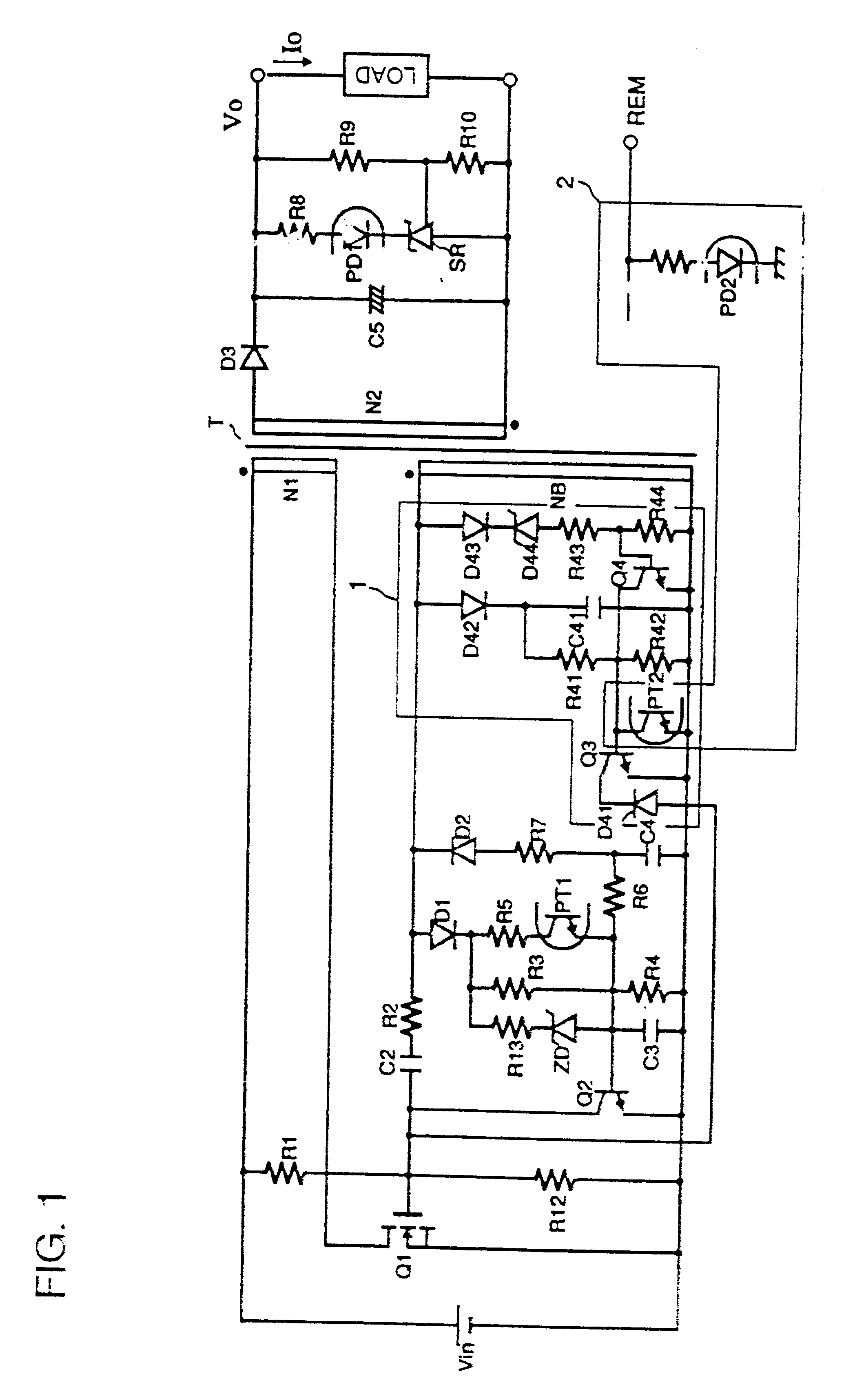
FIG. 1 is a circuit diagram of the self-oscillation switching power supply apparatus. As shown in FIG. 1, a MOS-FET serving as a switching transistor Q1 is connected to a primary winding N1 of a transformer T and there is provided a feedback circuit from a feedback winding N.sub.B of the transformer T to the switching transistor Q1. A rectifying and smoothing circuit including a rectifying diode D3 and a smoothing capacitor C5 is connected to a secondary winding N2 of the transformer T. The output of the rectifying and smoothing circuit is connected to a voltage detecting circuit including a resistance voltage divider consisting of resistors R9 and R10, a shunt regulator SR, a light emitting element PD1 of a first photocoupler, and a resistor R8.

In FIG. 1, when a remote signal REM with a high-level value is applied from the outside to a light emitting element PD2 of...


PUM


Abstract

A self-oscillation switching power supply apparatus of the ringing choke converter type comprises a transformer T including a primary winding N1, a secondary winding N2, and a feedback winding NB; a switching transistor Q1 which oscillates in a self-oscillating fashion in response to a feedback signal from the feedback winding NB thereby turning on and off the current flowing through the primary winding; a rectifying and smoothing circuit connected to the secondary winding; an oscillation frequency control circuit including a control transistor Q3 for controlling a control signal input to the switching transistor Q1 thereby controlling the control transistor Q3 so as to extend the off-time in the self-oscillation period of the switching transistor Q1; and an oscillation frequency control disabling circuit for disabling the control of the control transistor Q3 in accordance with a remote signal.

Description

1. Field of the InventionThe present invention relates to a self-oscillation switching power supply apparatus.2. Description of the Related ArtA ringing choke converter is widely used as a self-oscillation switching power supply apparatus. FIG. 9 is a circuit diagram of a ringing choke converter (hereinafter referred to as an RCC) according to a conventional technique. As shown in FIG. 9, a switching transistor Q1 is connected in series to a primary winding N1 of a transformer T. A control circuit including a phototransistor PT serving as a photosensing element of a photocoupler is connected to a feedback winding N.sub.B of the transformer. A control transistor Q2 is connected between the gate and the source of the switching transistor Q1.A rectifying and smoothing circuit including a rectifying diode D3 and a smoothing capacitor C5 is disposed between two terminals of a secondary winding N2 of the transformer T. The output of this rectifying and smoothing circuit is connected to a ...

Claims


Application Information

Patent Timeline
Patent Type & Authority Patents(United States)
IPC IPC(8): H02M3/24H02M3/338
CPCH02M3/3385
Inventor NAKAHIRA, KOJIOKAMURA, RYUJITANI, RYOTANISHIDA, AKIO
Owner MURATA MFG CO LTD
Why Eureka
Try Eureka