Electromagnetic energy distributions for electromagnetically induced mechanical cutting

a technology of electromagnetic energy distribution, which is applied in the field of laser output optical energy distribution, can solve the problems that the pulse shape and frequency of typical prior art output optical energy distribution is not particularly suited to provide optical electromagnetically induced mechanical cutting

Inactive Publication Date: 2001-09-11
BIOLASE TECH INC
View PDF33 Cites 94 Cited by
  • Summary
  • Abstract
  • Description
  • Claims
  • Application Information

AI Technical Summary

Problems solved by technology

As a result of the unique interactions of the output optical energy with the atomized fluid particles, typical prior art output optical energy

Method used


Image

  • Electromagnetic energy distributions for electromagnetically induced mechanical cutting
  • Electromagnetic energy distributions for electromagnetically induced mechanical cutting
  • Electromagnetic energy distributions for electromagnetically induced mechanical cutting

Examples


Embodiment Construction

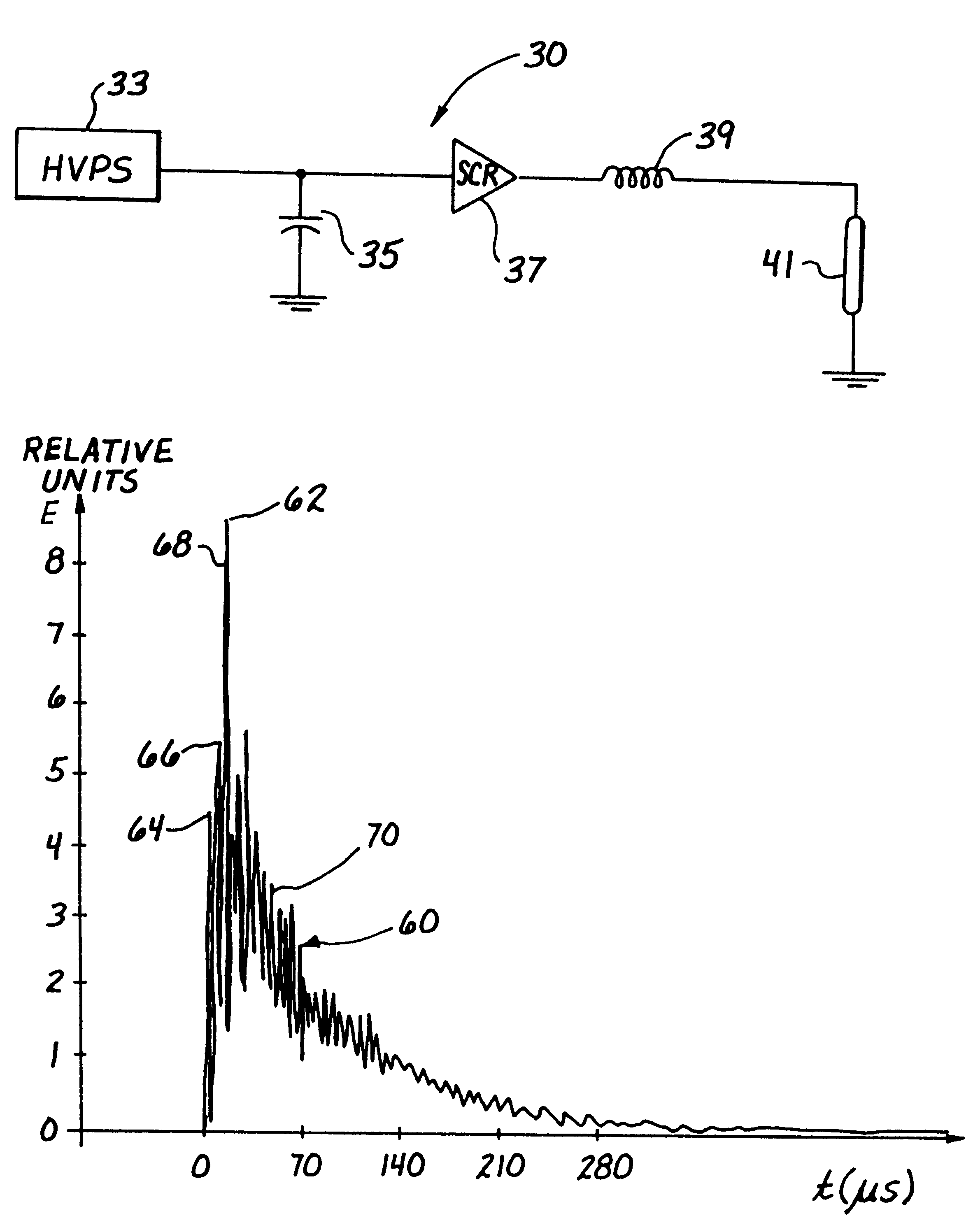
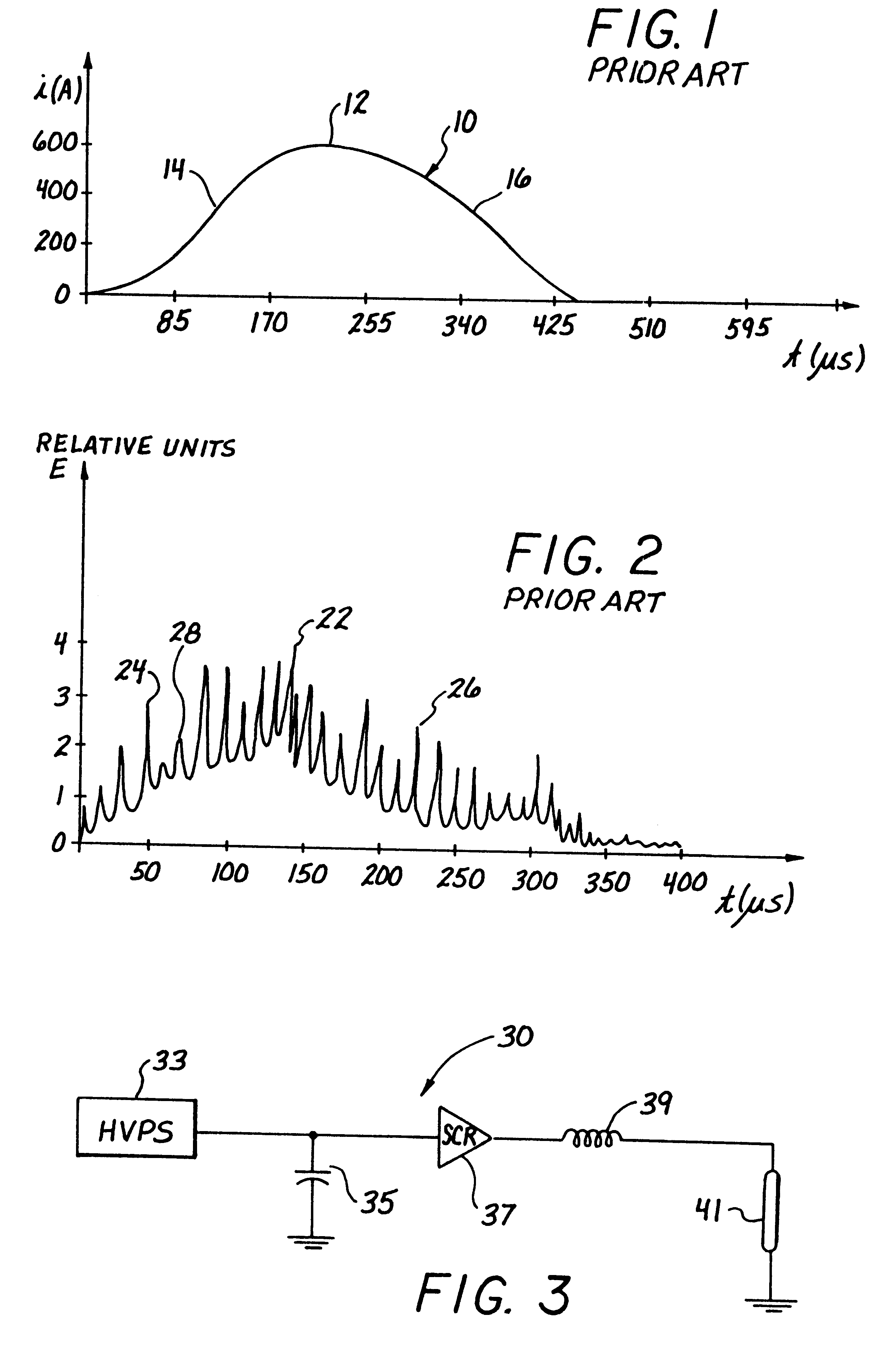
Referring more particularly to the drawings, FIG. 1 illustrates a plot of flashlamp-driving current versus time according to the prior art. The flashlamp-driving current 10 initially ramps up to a maximum value 12. The initial ramp 14 typically comprises a slope (current divided by time) of between 1 and 4. After reaching the maximum value 12, the flashlamp-driving current 10 declines with time, as illustrated by the declining current portion 16. The prior art flashlamp-driving current 10 may typically comprise a frequency or repetition rate of 1 to 15 hertz (Hz). Additionally, the flashlamp-driving current 10 of the prior art may typically comprise a pulse width greater than 300 microseconds. The full-width half-max value of the flashlamp-driving current 10 is typically between 250 and 300 microseconds. The full-width half-max value is defined as a value of time corresponding to a length of the full-width half-max range plotted on the time axis. The full-width half-max range is def...


PUM

PropertyMeasurementUnit
Timeaaaaaaaaaa
Timeaaaaaaaaaa
Timeaaaaaaaaaa

Abstract

Output optical energy pulses including relatively high energy magnitudes at the beginning of each pulse are disclosed. As a result of the relatively high energy magnitudes which lead each pulse, the leading edge of each pulse includes a relatively large slope. This slope is preferably greater than or equal to 5. Additionally, the full-width half-max value of the output optical energy distributions are between 0.025 and 250 microseconds and, more preferably, are about 70 microseconds. A flashlamp is used to drive the laser system, and a current is used to drive the flashlamp. A flashlamp current generating circuit includes a solid core inductor which has an inductance of 50 microhenries and a capacitor which has a capacitance of 50 microfarads.

Description

1. Field of the InventionThe present invention relates generally to lasers and, more particularly, to output optical energy distributions of lasers.2. Description of Related ArtA variety of laser systems are present in the prior art. A solid-state laser system generally comprises a laser rod for emitting coherent light and a stimulation source for stimulating the laser rod to emit the coherent light. Flashlamps are typically used as stimulation sources for Erbium laser systems, for example. The flashlamp is driven by a flashlamp current, which comprises a predetermined pulse shape and a predetermined frequency.The flashlamp current drives the flashlamp at the predetermined frequency, to thereby produce an output flashlamp light distribution having substantially the same frequency as the flashlamp current. This output flashlamp light distribution from the flashlamp drives the laser rod to produce coherent light at substantially the same predetermined frequency as the flashlamp curren...

Claims


Application Information

Patent Timeline
IPC IPC(8): B23K26/06B23K26/00B23K26/38B23K26/14H01S3/092H01S3/0915H05B37/00
CPCB23K26/0069H01S3/092B23K26/1417B23K26/38B23K26/063A61B18/20B23K26/0622B23K26/146B23K26/356
Inventor RIZOIU, IOANA M.KIMMEL, ANDREW I.
Owner BIOLASE TECH INC
Why Eureka
Try Eureka