Needleless valve

a needleless valve technology, applied in the direction of couplings, process and machine control, instruments, etc., can solve the problems of increasing the risk of infection each, pain for patients, and inability to maintain the appropriate sterile seal

Inactive Publication Date: 2001-09-18
CAREFUSION 303 INC
View PDF95 Cites 164 Cited by
  • Summary
  • Abstract
  • Description
  • Claims
  • Application Information

AI Technical Summary

Problems solved by technology

The presence of the valve avoids the necessity of using direct injection of the patient each time the medication is to be administered, which would be both painful to the patient and also increase the risk of infection each time the skin was penetrated.
Repeated piercing of the plug with the hypodermic needles eventually damages the plug sufficiently that it cannot maintain the appropriate sterile seal.
Further, since the valve / receiver devices are normally quite small, the plug is even smaller, often less than 1 / 4 inch (6 mm) in diameter.
In addition, it was not uncommon for hypodermic needles to break off in the plug during or before administration of the liquid, thus usually becoming lodged in the rubber plug and requiring the administrator to take time to remove the broken needle.
Further, such breakage also commonly caused the loss of all or a portion of the medication or other liquid in the syringe and, of course, not properly administered to the patient.
Such problems were particularly common in situations where the medical personnel were required to act very rapidly, such as in emergency room and emergency medical administration settings.
The accidental piercing of the skin of the doctor or nurse raised critical problems.
If such occurred before administration of the medication to the patient, the medication, or at least a portion of it, was injected into the nurse or doctor, which not only deprived the patient of the medication, but in fact might be quite harmful to the physician or nurse.
While this was a severe problem at any time, it became a truly critical problem as various highly infectious or virulent diseases became more prevalent in the population.
While the "needleless" concept has been well known and is quite simple, implementation of the concept in practice has been quite difficult.
While such devices have worked well for the most part, they have been found to have some serious deficiencies.
This produces a suctioning effect which often causes the patient's venous blood to be drawn into the catheter where it remains and can clot, thus preventing flow through the catheter.
This, of course, is a major problem in emergency situations, whether in an emergency room or when a patient on IV suffers some sort of relapse or seizure or other critical condition and medication must be administered through the IV without delay.
In ordinary situations this at least requires the time of a nurse and is a discomfort for the patient.
In many cases, however, reinsertion is a problem that requires a doctor's intervention, as for instance where an new acceptable insertion site is difficult to find or the patient does not tolerate needle insertions well.
Thus reinsertion presents a significant cost event for the medical team and subsequently for the patient.

Method used


Image

  • Needleless valve
  • Needleless valve
  • Needleless valve

Examples


Embodiment Construction

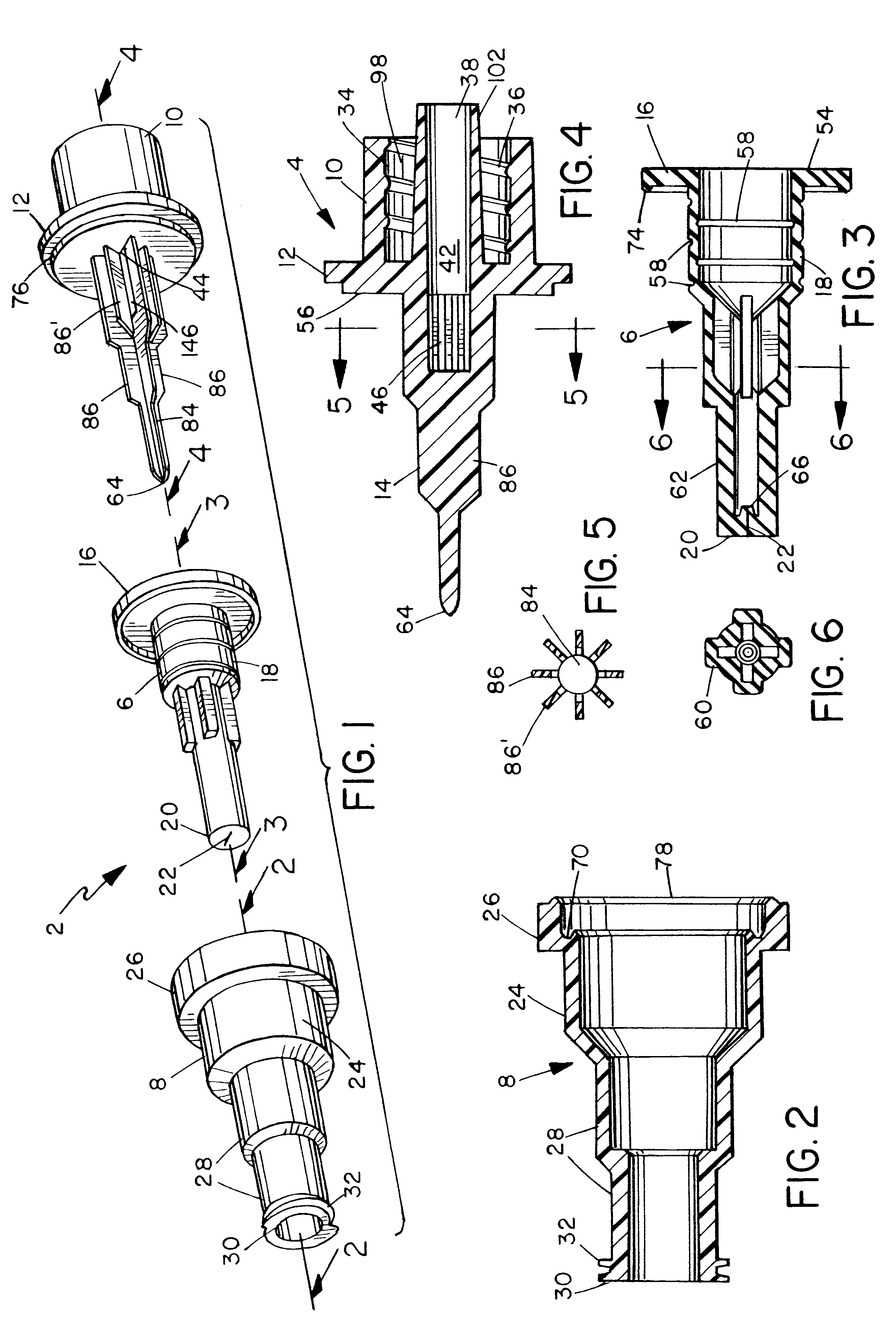
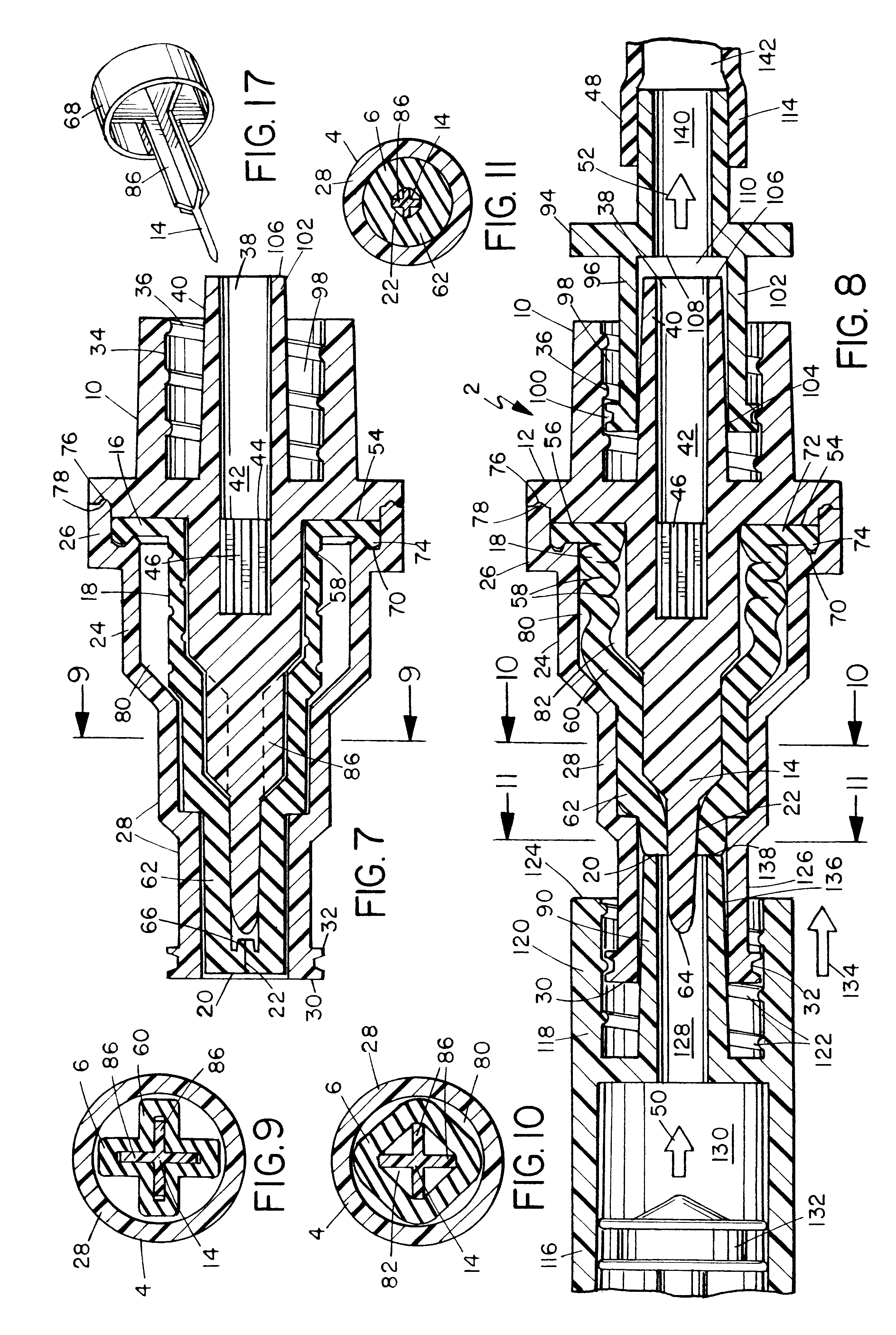
The device is best understood by reference to the drawings. For the purposes of description herein, the following conventions of direction will be maintained. The terms "upstream" and "downstream" will be with respect to the normal direction of fluid flow during administration of medication or other liquid through the valve of the present invention to a patient or other receiver. This is indicated in FIG. 8 by the flow arrows 50 (upstream) and 52 (downstream). Similarly, the terms "distal" and "proximal" will be used with respect to the patient or other receiver, such that the upstream end of the device is also sometimes referred to as the distal end, while the downstream end is also sometimes referred to as the proximal end.

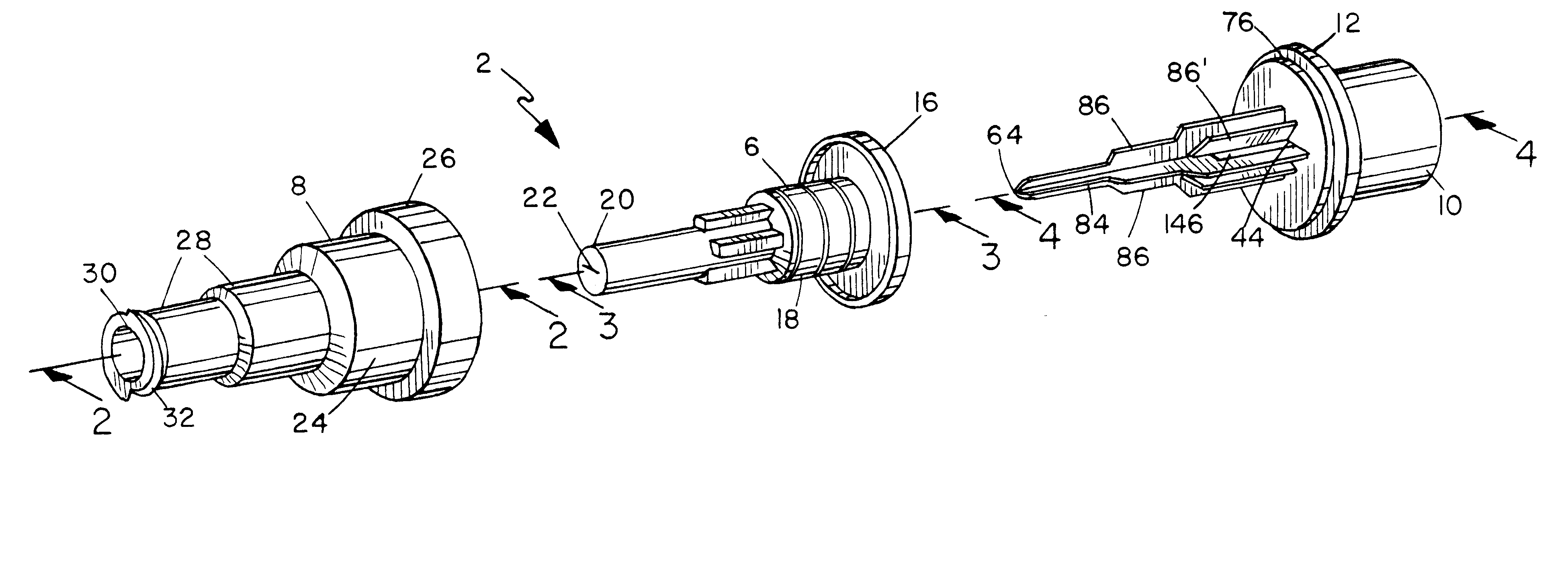
One embodiment of the overall device 2 is shown in FIG. 1, separated into three components: a base 4, plug 6 and housing 8. The principal features of each of the parts may also be seen in FIG. 1. The base 4 consists of a connector 10 which connects the device wi...


PUM


Abstract

A needless valve is described which avoids the suctioning problems of the prior needleless devices upon deactivation and which preferably provides a positive self-purging effect. The valve is self-purging at the end of an administration cycle, avoiding clogging of attached catheters or other devices, and ensures that substantially all of liquid received into the valve is delivered to the receiver. The valve is also extremely simple in design and easy to construct and assemble, since it consists of only three pieces. The valve has a base with a connector for fluid communication attachment to tubing or other device, a solid elongated fluid channeling rod, and an internal fluid flow conduit; a flexible hollow expandable and contractible plug fitting over and moveable along the rod; and a tubular housing fitting over the plug and attached to the base. When the valve is activated by insertion of a nozzle of a fluid source, the rod and plug wall cooperate so that as the plug retracts along the rod, it is stretched and its interior expanded. Upon deactivation, the plug contracts, the interior volume decreases, and the resiling plug wall forces residual fluid within the valve to be expelled through the outlet, purging the residual fluid from the valve. No negative pressure is formed, so no suctioning of blood or other fluid from a patient or receiver occurs.

Description

1. Field of the InventionThe invention herein relates to valves and connectors, such as those use in medical liquid flow applications such as intravenous (IV) administration of medications. More particularly it relates to needleless valves for such applications.2. Description of the Prior ArtThere are many instances, particularly in the medical field, where quantities of liquid must be moved from a source of the liquid to a liquid conduit system under restricted and usually sterile conditions. A principal example is the administration of medication or other liquids to a patient intravenously. When the intravenous administration is to be conducted at periodic intervals over a extended period of time, the conventional practice is to insert a catheter into the patient's vein, usually through the patient's forearm, and leave the catheter in place with a portion extending out of the patient's arm and terminating in a valve (receiver) for periodic connection to the liquid source as requir...

Claims


Application Information

Patent Timeline
Patent Type & Authority Patents(United States)
IPC IPC(8): A61M39/26A61M39/00A61M5/168
CPCA61M39/26A61M2039/263A61M2039/262A61M2039/267A61M39/22
Inventor DOYLE, MARK CHRISTOPHER
Owner CAREFUSION 303 INC
Why Eureka
Try Eureka