Gutter liner apparatus

Inactive Publication Date: 2001-09-25
CANGIALOSI
View PDF27 Cites 26 Cited by
  • Summary
  • Abstract
  • Description
  • Claims
  • Application Information

AI Technical Summary

Problems solved by technology

Such accumulation, if not removed leads to interruption of the normal drainage flow that the gutter system was designed to accomplish.
If left uncorrected, damage to the gutter system and/or the building may occur.
During periods of rainfall, the run-off wat

Method used


Image

  • Gutter liner apparatus
  • Gutter liner apparatus
  • Gutter liner apparatus

Examples


Embodiment Construction

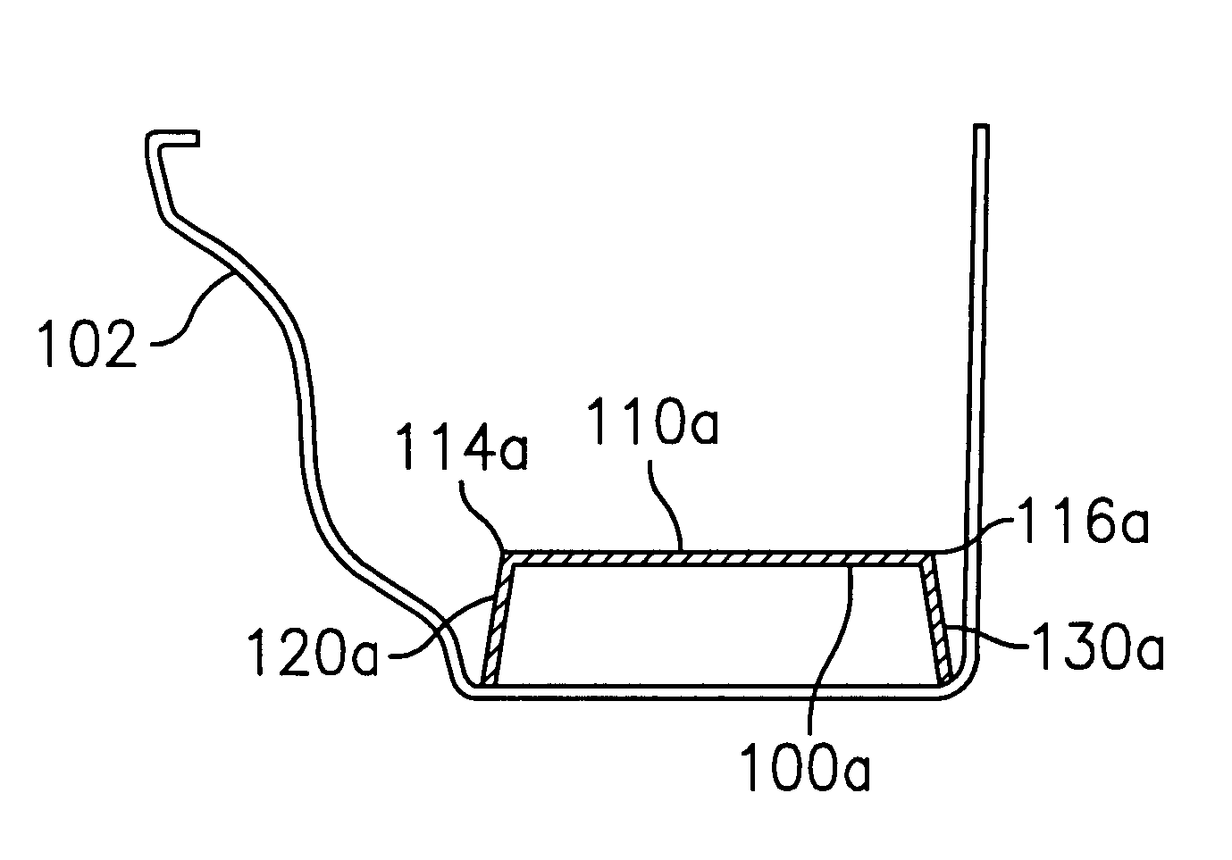
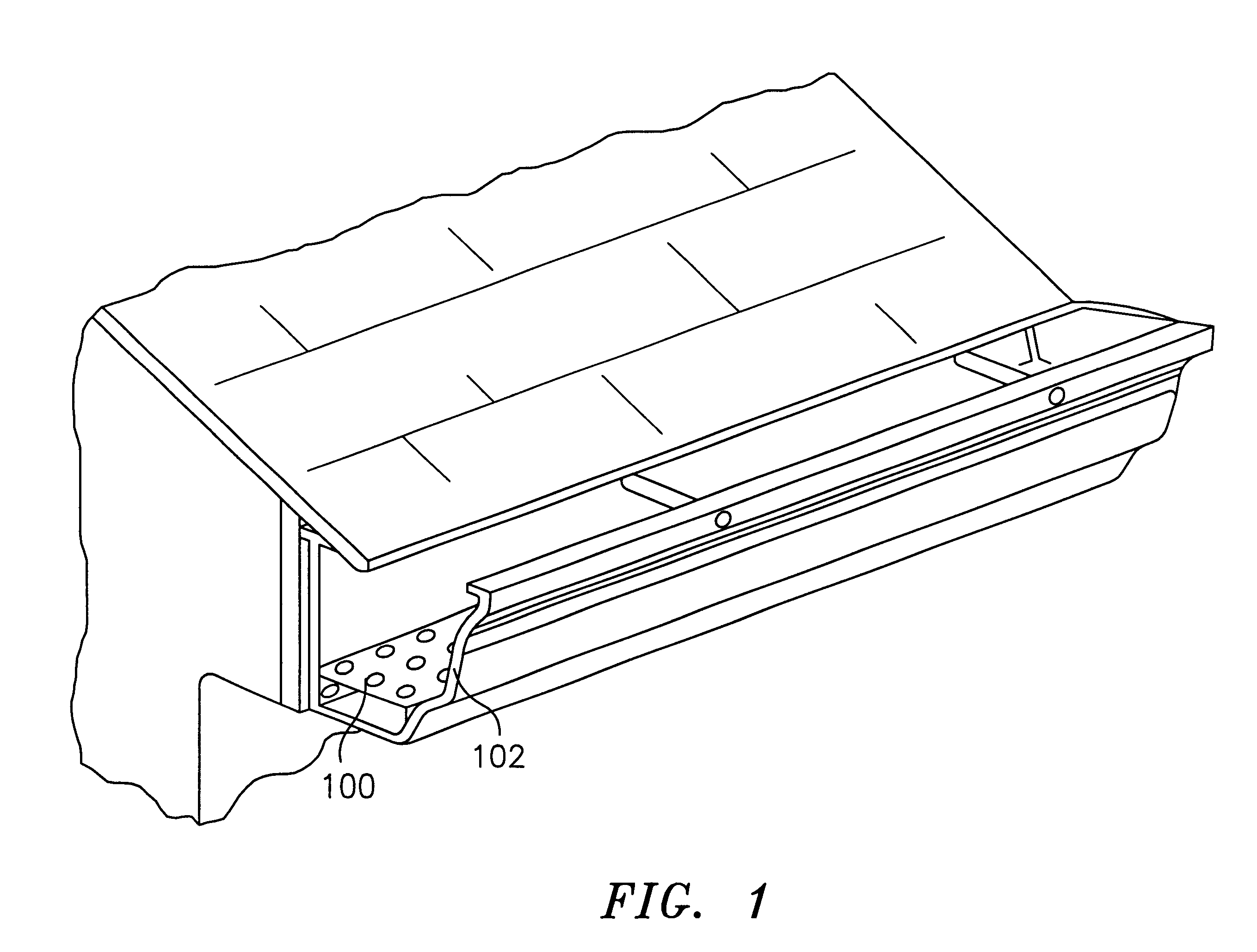
Referring now to the drawings in detail, and initially to FIG. 1, a gutter liner apparatus designated by reference numeral 100 is shown installed in a gutter 102. In this configuration, gutter liner apparatus 100 rests on the bottom of the gutter and preferably extends less than half way up the height of the gutter.

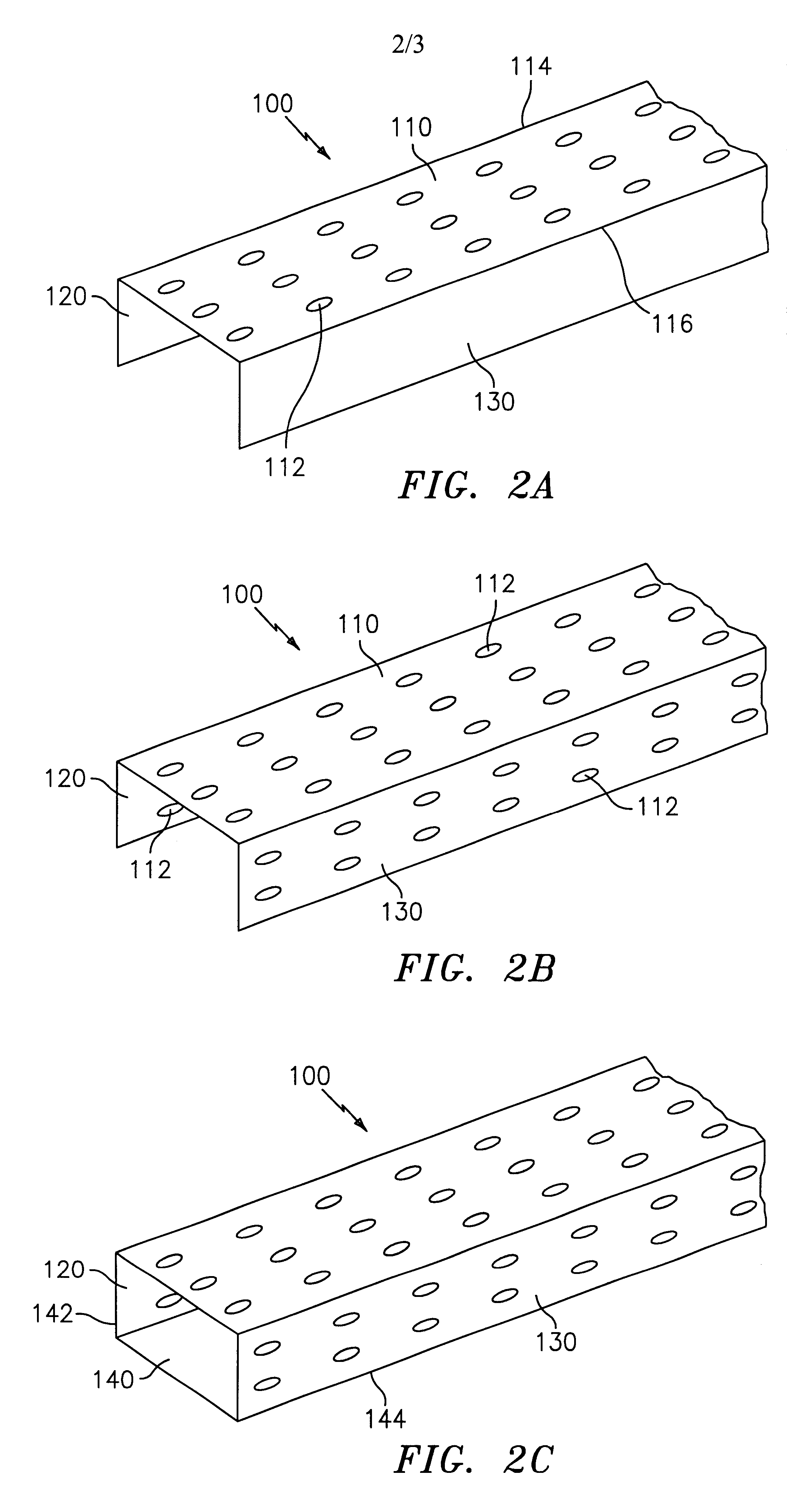
Referring now to FIG. 2A, gutter liner apparatus 100 is formed with an upper platform portion 110 that defines a first edge 114 and second edge 116. A first sidewall 120 extends downwardly from first edge 114 and second sidewall 130 extends from second edge 116. The angles between platform portion 110 and first sidewall 120 and platform portion 110 and second sidewall 130 can vary depending on the specific configuration of gutter liner apparatus. In this configuration, first sidewall 120 and second sidewall 130 are orthogonal to upper platform surface 110.

Gutter liner apparatus 100 has perforations 112 formed in platform portion 110. Perforations 112 formed can vary in fr...


PUM

PropertyMeasurementUnit
Heightaaaaaaaaaa
Heightaaaaaaaaaa
Flow rateaaaaaaaaaa

Abstract

Gutter liner apparatus having a perforated upper platform surface that extends the width of the gutter and is supported by two sidewalls that extend down from the front and back edges of the upper platform so that the platform is situated in the lower half of the gutter upon installation therein. The perforations in the upper platform surface exclude leaf type debris from blocking the drainage flow of the gutter. The sidewalls can vary from being perpendicular to the upper platform to being flared outwardly away from an axis perpendicular to the upper platform to cause them to bias against the inner surfaces of the gutter. Other geometries provide additional advantages under selected circumstances. Perforations can be only on the upper platform surface or also on the sidewalls.

Description

1. Technical FieldThe present invention relates to a gutter liner apparatus which excludes leaf and other debris from interrupting the drainage flow in a building's gutter system.2. Description of Related ArtThe accumulation of leaves and other matter in the gutter system of buildings is a constant concern for the building owner. Such accumulation, if not removed leads to interruption of the normal drainage flow that the gutter system was designed to accomplish. If left uncorrected, damage to the gutter system and / or the building may occur.During periods of rainfall, the run-off water from the roof quickly fills and overflows the clogged gutter system thereby totally defeating the function and purpose of the gutter system. During periods of heavy snow accumulation, the water generated from the accumulated snow which usually melts during daylight hours in direct sunlight fills the clogged gutters only to freeze again at night or when temperatures dip below the freezing point. This cy...

Claims


Application Information

Patent Timeline
IPC IPC(8): E04D13/04E04D13/076
CPCE04D13/076
Inventor CANGIALOSI, SAL
Owner CANGIALOSI
Why Eureka
Try Eureka