Hydraulic circuit for forklift

a technology of hydraulic circuit and forklift, which is applied in the direction of fluid coupling, servomotor, coupling, etc., can solve the problems of difficult inching of the piston 218, small amount of oil is hardly supplied, and the inching of the fork is difficul

Inactive Publication Date: 2001-09-25
TOYOTA IND CORP
View PDF5 Cites 44 Cited by
  • Summary
  • Abstract
  • Description
  • Claims
  • Application Information

AI Technical Summary

Problems solved by technology

However, since both of the electric pumps 212 and 214 are on-off controlled, a very small amount of oil is hardly supplied to the piston in high response, so inching of the piston 218 is difficult if only the electric motor 214 is driven for the inching.
However, because the motor 222 is on-off controlled, a very small amount of oil is hardly supplied to the cylinder 224, so inching of the fork is difficult, which is same as the hydraulic circuit in FIG. 5.
Such arrangement is convenient for the inching of the fork, but inconvenient for the high speed lifting of the fork.

Method used


Image

  • Hydraulic circuit for forklift
  • Hydraulic circuit for forklift
  • Hydraulic circuit for forklift

Examples


embodiment

PREFERRED EMBODIMENT

Hereinafter, a preferred embodiment of the present invention will be explained with reference to attached drawings, but it is noted that the present invention is not limited to these embodiments and various modifications are possible within the scope of the present invention.

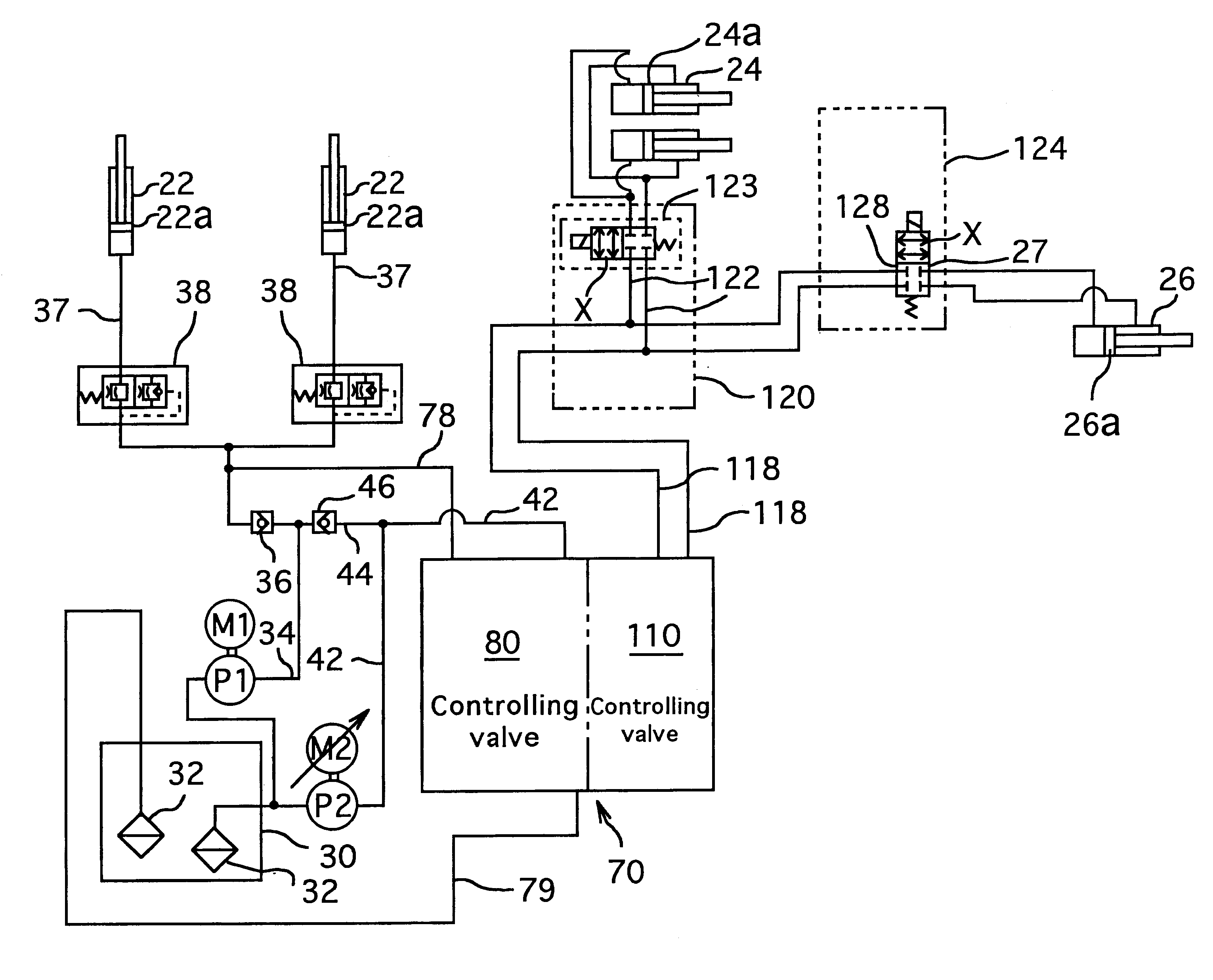
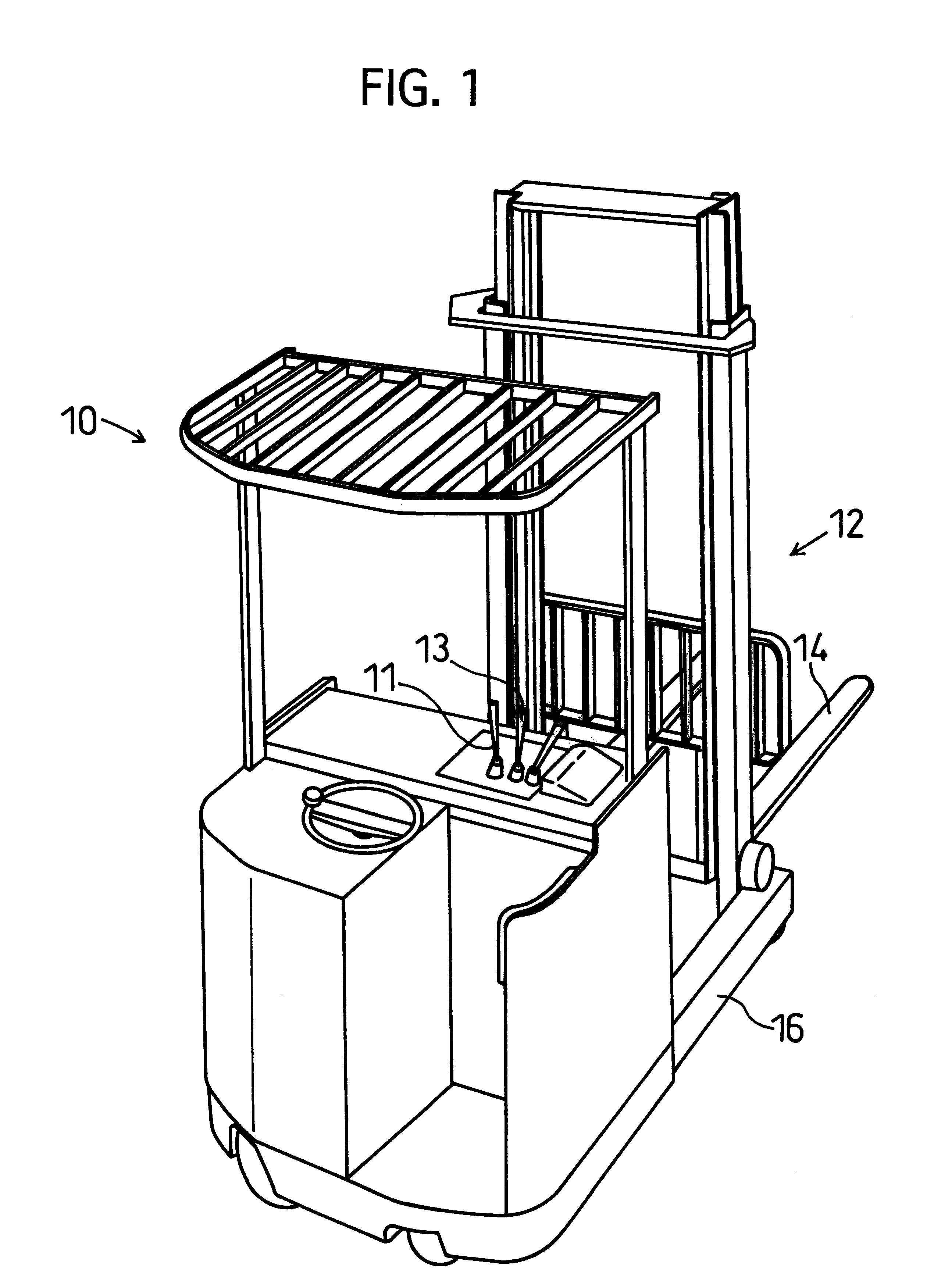
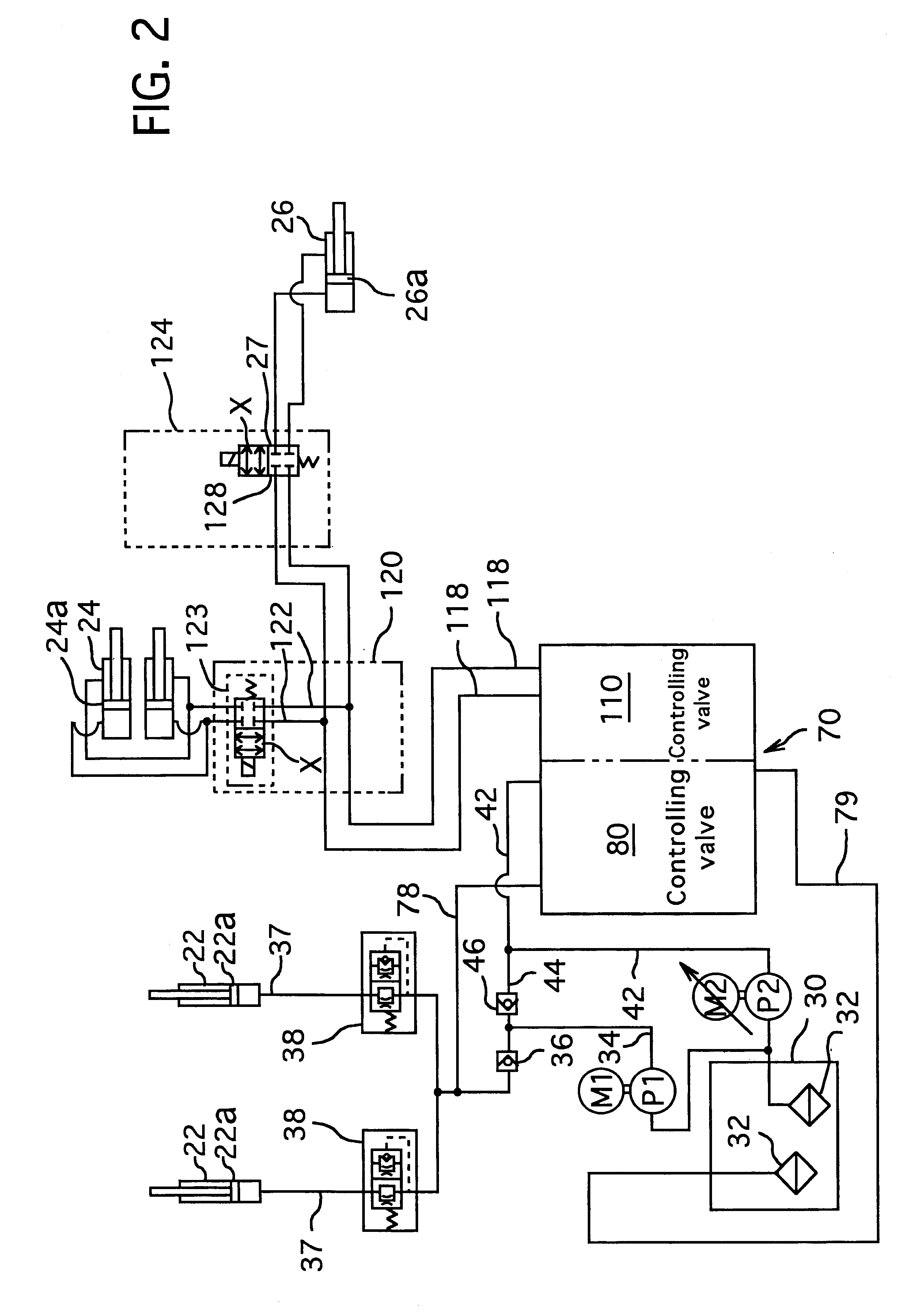
A forklift 10 show in FIG. 1 has, at front side thereof a lifting device 12 including a fork 14, reach mechanism 16 and tilt mechanism (not shown) which are respectively connected to a lift cylinder 22, reach cylinder 24 and, tilt cylinder 26 shown in FIG. 2.

Here, lift cylinder 22 is disposed vertically, and a piston 22a thereof is lifted when the hydraulic pressure is supplied to the bottom of lift cylinder 22, and is lowered by its own gravity. The reach cylinder 24 and tilt cylinder 26 are disposed horizontally, and pistons 24a and 26a thereof are shifted forwardly or rearwardly when the hydraulic pressure is supplied to one end or other end of each cylinder 24 or 26. All of these fork 14,...


PUM


Abstract

This invention relates to a hydraulic circuit for a forklift, and intends to lift a fork for lifting in high speed, or to inch the fork little by little, as occasion demands. In this hydraulic circuit, a first electric motor for driving a first electric motor disposed on a first route extending from a tank to a lift cylinder is on-off controlled. A check valve disposed on the first route downstream of the first hydraulic pump allows only an oil-flow from the oil tank to the lift cylinder. A second motor for driving a second electric motor disposed on a second route extending from a tank to a lift cylinder is PMW-controlled. A flow controlling valve is disposed on the second route downstream of the second hydraulic pump and including an electro-magnetic valve operated associating with the PMW-controlling of said second electric motor. A separating element hydraulically separates the check valve and the electro-magnetic valve of the flow controlling valve.

Description

DETAILED EXPLANATION OF THE INVENTION1. Field of the InventionThe present invention relates to a hydraulic circuit for a forklift, in particular it relates to the hydraulic circuit which can shift( lift) at least a fork for lift (hereinafter referred to "fork") over a long stroke in high speed, or can inch position of the fork little by little or gradually, as the occasion demands.2. Related Background ArtGenerally, a forklift has at a front side a lifting device including the fork for lifting a load, and this lift is lifted vertically by a hydraulic circuit. The hydraulic circuit generally includes passages or routes extending from a tank to a lift cylinder, a hydraulic pump for supplying an operating oil (hereinafter referred to "oil"), an electric motor for driving the hydraulic pump, the lift cylinder having a piston connected to the fork to lift it vertically, and a flow controlling valve.For lifting the load to a high position by lifting operation of the lifting device, it is ...

Claims


Application Information

Patent Timeline
Patent Type & Authority Patents(United States)
IPC IPC(8): B66F9/20B66F9/22F15B11/00F15B11/17F15B11/16
CPCB66F9/22F15B11/17F15B11/162F15B2211/78F15B2211/20546F15B2211/20576F15B2211/30505F15B2211/30515F15B2211/3111F15B2211/327F15B2211/40515F15B2211/426F15B2211/455F15B2211/6355F15B2211/7128F15B2211/7142F15B2211/75
Inventor KAMIYA, KAZUSHI
Owner TOYOTA IND CORP
Why Eureka
Try Eureka