

Emptying station for bulk bags, and process of emptying bulk bags in the station
Inactive Publication Date: 2001-09-25
DEGUSSA AG
View PDF11 Cites 43 Cited by
- Summary
- Abstract
- Description
- Claims
- Application Information
AI Technical Summary
Benefits of technology
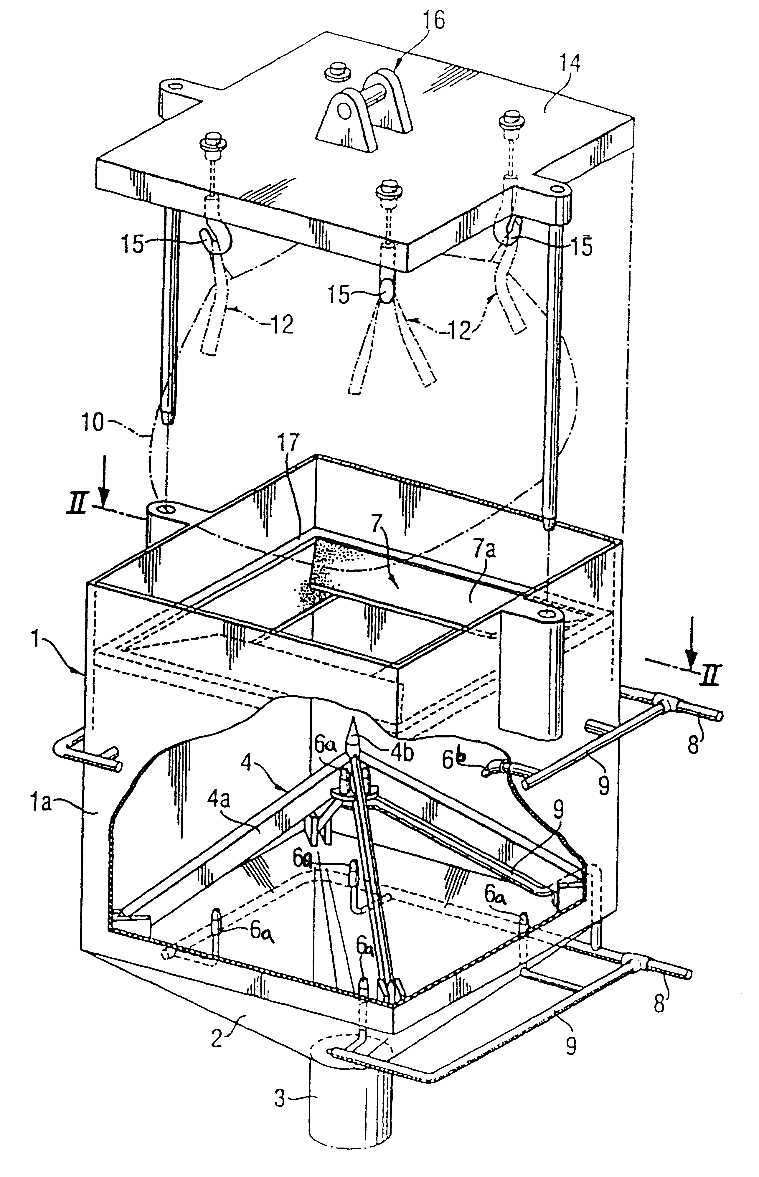
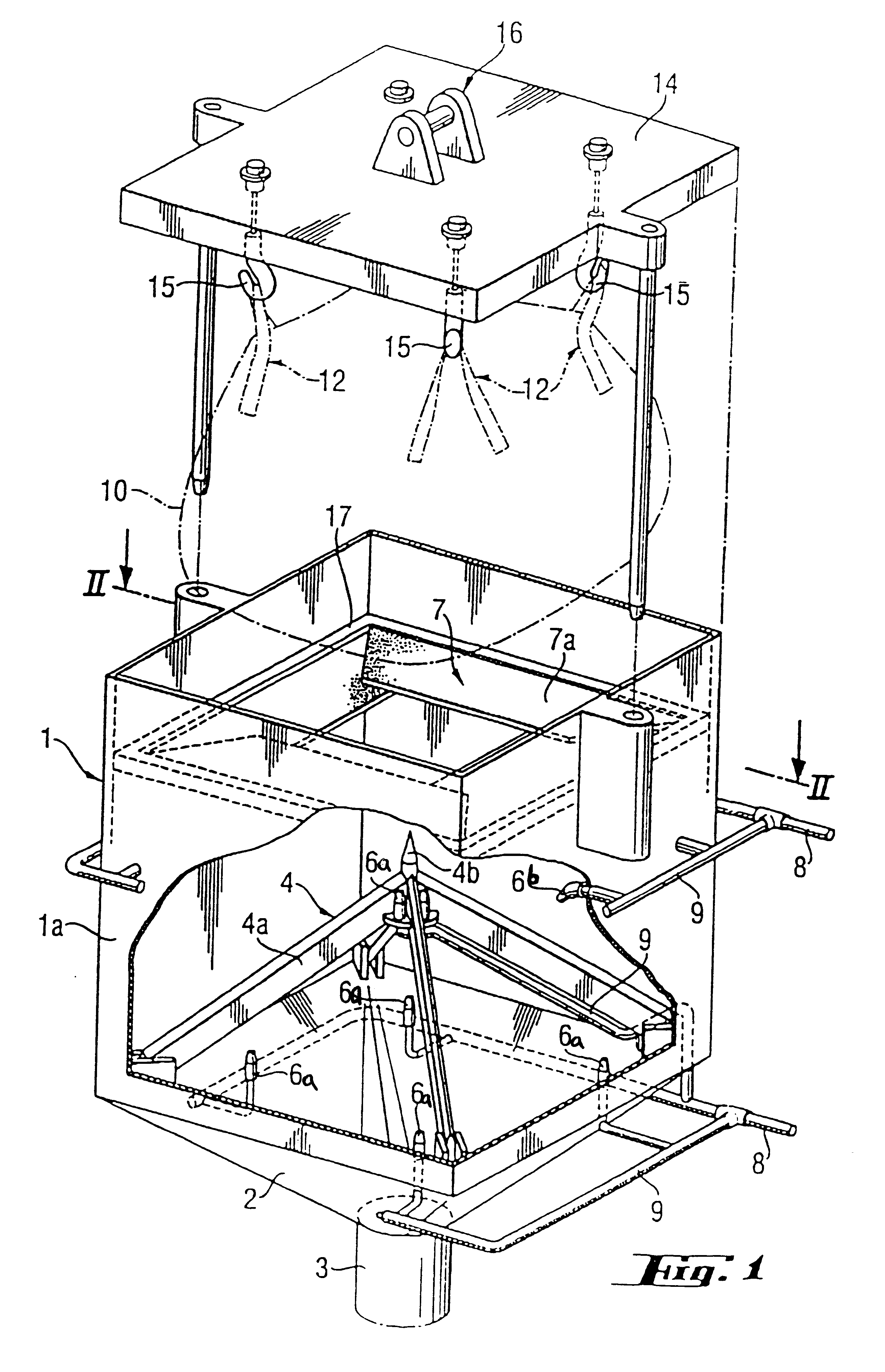
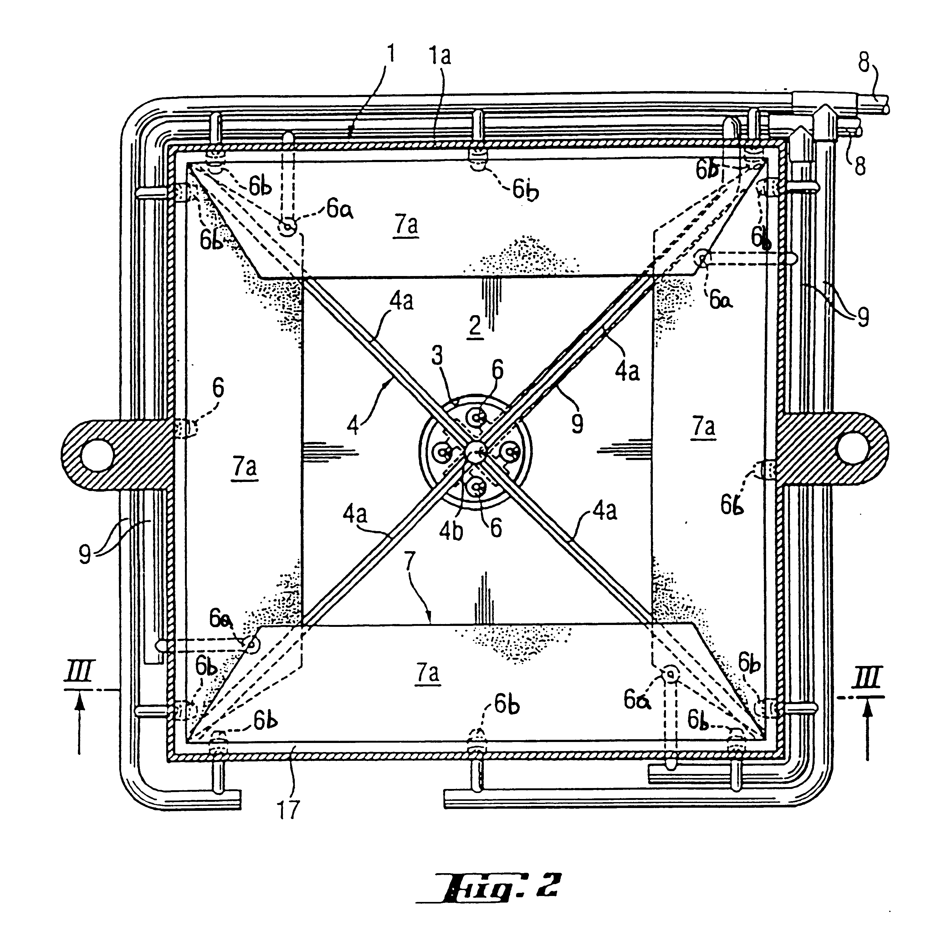
The height of the side walls 1a, measured from the base of the cutting subassembly 4, corresponds to at least the height of the bulk bag 10 and the outstretched suspenders 12. By providing the side walls 1a with a sufficient height, the entire filled bulk bag 10 can be accommodated in the receptacle body 1 and the top closure 14 can function as a lid, closing the top opening of the receptacle body 1. The cross section of the receptacle body 1 corresponds substantially to the cross section of the filled bulk bag 10, with an additional wall gap being present between the filled bulk bag 10 and the inner surfaces of the walls 1a to facilitate handling of the bulk bag 10 during raising and lowering operations.
To prevent dust from escaping from the receptacle body 1, the receptacle body 1 includes a sealing structure 7 for sealing the gaps between the bulk bag 10 and the side walls 1a. As referred to herein, the sealing structure 7 can include strips located uniformly at one height as shown in FIG. 1, or a plurality of sealing strips arranged at different heights on the side walls 1a. The sealing structure 7 can include a single-part sealing lip or multi-part sealing lips. In the case of emptying stations with rectangular box cross sections, such as illustrated in FIG. 1, a suitable sealing structure 7 comprises a sealing plate 7a of a flexible material fixed to a flange 17 on each of the side walls 1a. The material for making the sealing plates 7a can be made, for example, of one of more of the following: natural and / or synthetic rubbers; flexible plastics such as polyolefins and polyamides; and silicone-rubber. The sealing plates 7a are pressed downwards upon lowering of the bulk bag 10 and thus seal the gap due to their positioning and flexibility and elasticity.
It is expedient for the rinsing agent to be a solvent or suspending agent in the intended reaction. The quantity of rinsing agent entering the reactor (or other equipment downstream from outlet 3) in the form of the liquid rinsing agent is accordingly taken into account when the reactor is filled with liquid agent. Rinsing of the inside of the bulk bag not only prevents potential hazards, such as may arise during disposal of an unrinsed bulk bag, but at the same time makes the material supplied in the bulk bag available to the desired reaction without loss of material. After emptying the bulk bag 10, if required the exterior of the bulk bag also can be cleaned by means of spray nozzles incorporated in the side walls 1a and / or on the top closure 12. Once the rinsing process is complete, the emptied and rinsed bulk bag 10 is withdrawn from the receptacle body 10 by means of the carrier device 16. If organic solvents are used for rinsing, it is expedient to blow air through the inside of the bulk bag 10 after rinsing thereof, to remove any solvent residues (not illustrated).
Bulk bags 10, as shown in FIG. 4 and which are suitable for filling with hazardous materials, generally comprise an inner sack 18 and an outer sack 19. The inner sack 18 serves primarily to protect the bulk bag contents, but also should be sufficiently strong to hold the contents of the bulk bag 10. The outer sack 19 serves primarily to provide mechanical strength. The inner and outer sacks 18 and 19 are conventionally closed separately, by tying with tape 13 and / or other suitable means, such as adhesive or welding. Standard bulk bags 10 additionally comprise a plurality of suspenders 12, illustrated in FIG. 4 in the form of lifting straps 12a. The fixing seams 21 provide sufficient dimensional stability and strength to maintain the bottom 20 substantially flat.
The emptying station according to the invention is distinguished from known stations by the simplicity and reliability of its structure. Occupational hygiene problems arising hitherto during the handling of hazardous materials are prevented. The contents of the bulk bag are fed to a reactor or other equipment through the outlet without loss of materials, since dust and the like are contained. Although not limited to any particular use, the emptying station according to the invention may be used for emptying bulk bags filled with cyanuric chloride, in which case water is preferably used as the rinsing agent, since many reactions involving cyanuric chloride are performed in the presence of water.
Problems solved by technology
Although this device allows safe emptying of powder-form bulk material, such as cyanuric chloride, handling of bulk materials with this device is rather complex.
Another drawback of the device disclosed in U.S. Pat. No. 5,944,070 is that no provision is made for rinsing the emptied bulk bag before disposal of the emptied bulk bag.
However, the rubber sleeve is only partially effective, making devices equipped with the rubber sleeve unsatisfactory for emptying bulk bags filled with hazardous materials.
Such emptying stations also lack means for rinsing out the bulk bag with a liquid rinsing agent immediately after emptying thereof.
The absence of an effective rinsing means allows contents of the bulk bag to remain adhered to the sack wall after the emptying operation is complete, since no rinsing means is provided for dissolving or rinsing the residual contents away.
Method used
View moreImage
Smart ImageViewing Examples

Examples
Embodiment Construction
has been provided for the purpose of explaining the principles of the invention and its practical application, thereby enabling others skilled in the art to understand the invention for various embodiments and with various modifications as are suited to the particular use contemplated. This description is not intended to be exhaustive or to limit the invention to the precise embodiments disclosed. Modifications and equivalents will be apparent to practitioners skilled in this art and are encompassed within the spirit and scope of the appended claims.
Login to View More PUM
| Property | Measurement | Unit |
|---|---|---|
| Flexibility | aaaaa | aaaaa |
| Width | aaaaa | aaaaa |
| Height | aaaaa | aaaaa |
Abstract
This emptying station is suited for emptying contents from bulk bags, especially bulk bags containing particulate hazardous materials as their contents. The emptying station includes a bulk-bag receptacle body having a top opening and bottom outlet, a bulk-bag cutting subassembly in the receptacle body, a raisable and lowerable top closure, and a sealing structure. The cutting subassembly includes at least three cutters each having an associated blade facing upwards, with the cutters collectively arranged to define a pyramid having an apex, and puncture pin positioned at the apex to point upwardly. In operation, a bulk bag is suspended from the top closure, then lowered with the top closure to pass the bulk bag into the receptacle body and cause the substantially flat bottom of the bulk bag to be pieced by the puncture pin and cut by the blades of the cutters to start emptying contents from the bulk bags to the bottom outlet. The sealing structure seals gaps formed between inner surfaces of the side walls and the bulk bag to prevent dust from escaping through the top opening. As the bulk bag is emptied, the top closure continues to lower until the top closure is positioned in a closed state in the top opening. Spray nozzles are preferably arranged in the receptacle body for external and / or internal rinsing of the emptied bulk bag.
Description
This application relates to German Application DE 199 37 700.6, filed Aug. 10, 1999, the disclosure of which is incorporated herein by reference.1. Field of the InventionThe invention relates to an emptying station for bulk bags, in particular for bulk bags containing particulate hazardous materials, such as cyanuric chloride. The emptying station of this invention is especially useful for emptying bulk bags in a dust-free, safe manner and for rinsing the emptied bags.2. Description of the Related ArtVarious devices are known for emptying bulk bags, which as referred to herein mean large packaging containers which have in particular a capacity of from 100 to 1000 kg and are made of single-ply or multi-ply sacking material. U.S. Pat. No. 5,944,070 discusses one such device, which is purportedly useful for preventing problems arising during emptying of a bulk bag comprising an inner sack and an outer sack. The emptying device comprises a double-tube structure having an inner tube and ...
Claims
Login to View More Application Information
Patent Timeline
 IPC IPC(8): B65B69/00
CPCB65B69/0008B65B69/00
InventorSCHMIDT, MANFREDOHLEMACHER, JURGENEHRLICH, JOHANNES
OwnerDEGUSSA AG