Heater control device and method to save energy

a control device and heating device technology, applied in the direction of lighting and heating equipment, process and machine control, instruments, etc., can solve the problems of significant environmental energy loss, no a priori knowledge of the present or future need for hot water, and portion of energy that must be restored is not saved

Inactive Publication Date: 2001-09-25
STETTIN DANIEL R +1
View PDF17 Cites 178 Cited by
  • Summary
  • Abstract
  • Description
  • Claims
  • Application Information

AI Technical Summary

Problems solved by technology

This results in significant energy losses to the environment during extended periods of non-use of hot water, which would otherwise be significantly reduced were the heater in the switched off condition.
It is noteworthy that when tank water temperatures are reduced, there are savings in energy that accrue over time due to the difference in tank to ambient temperature; however, the water that has cooled during this period must ultimately be returned to the normal elevated operating temperature and therefore this portion of energy that must be restored is not saved.
This method, although possibly providing some energy savings, suffers from an important drawback in that this control has no a priori knowledge of the present or future need for hot water.
It is noteworthy that if the first user experiences a sufficient volume of available hot water after a long period of non use then the control has not saved an appreciable amount of energy.
A further disadvantage of the Bartok method is the inability of the control to predict non use of hot water and thus to allow the using up of hot water from the tank during periods just prior to a prolonged period of non use without triggering the "raise the thermostat set point condition".
As most modem water heaters are fitted with heat traps to prevent heat losses from conduction and convection of heated water from both the exit and inlet pipes, a small volume of water use will raise the thermostat set point for a long period; this resulting from the inability of the inlet and exit pipes to approach each other's temperatures, especially when well insulated from the environment (as Bartok suggests) and may render the control inoperative.
Another disadvantage of this scheme occurs when the ambient in the space (surrounding the water heater) is heated during the day, and left unheated at night.
Under these conditions the water temperature in the inlet pipe could vary by 35.degree. F. making the setting of the threshold for raising and lowering the thermostat "set" point and its associated hysteresis impractical to determine.
Also, the heater inlet pipe may be subject to a long pipe run within a heated space, such as might occur in an office complex or industrial setting, thus rendering the inlet temperature constant and since the functioning of the control makes use of the dropping inlet water temperature relative to the exit water temperature, making it difficult to find the correct threshold temperature difference to switch to the high temperature setting; as a result the control may not function as intended.
Scott states "During periods of low use, heat energy is wasted if the temperature of the water remains at a high level.
However, a heat trap on the inlet pipe (commonly installed on modem water heaters) will prevent the inlet pipe to refill with heated water from the tank and the control will not operate as implied.

Method used


Image

  • Heater control device and method to save energy
  • Heater control device and method to save energy
  • Heater control device and method to save energy

Examples


Embodiment Construction

.

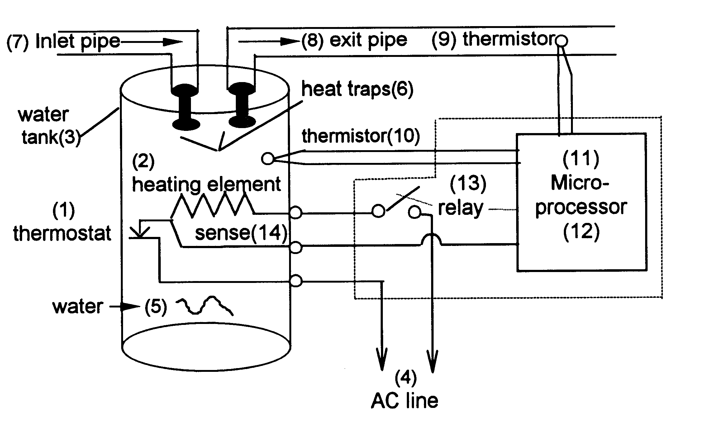
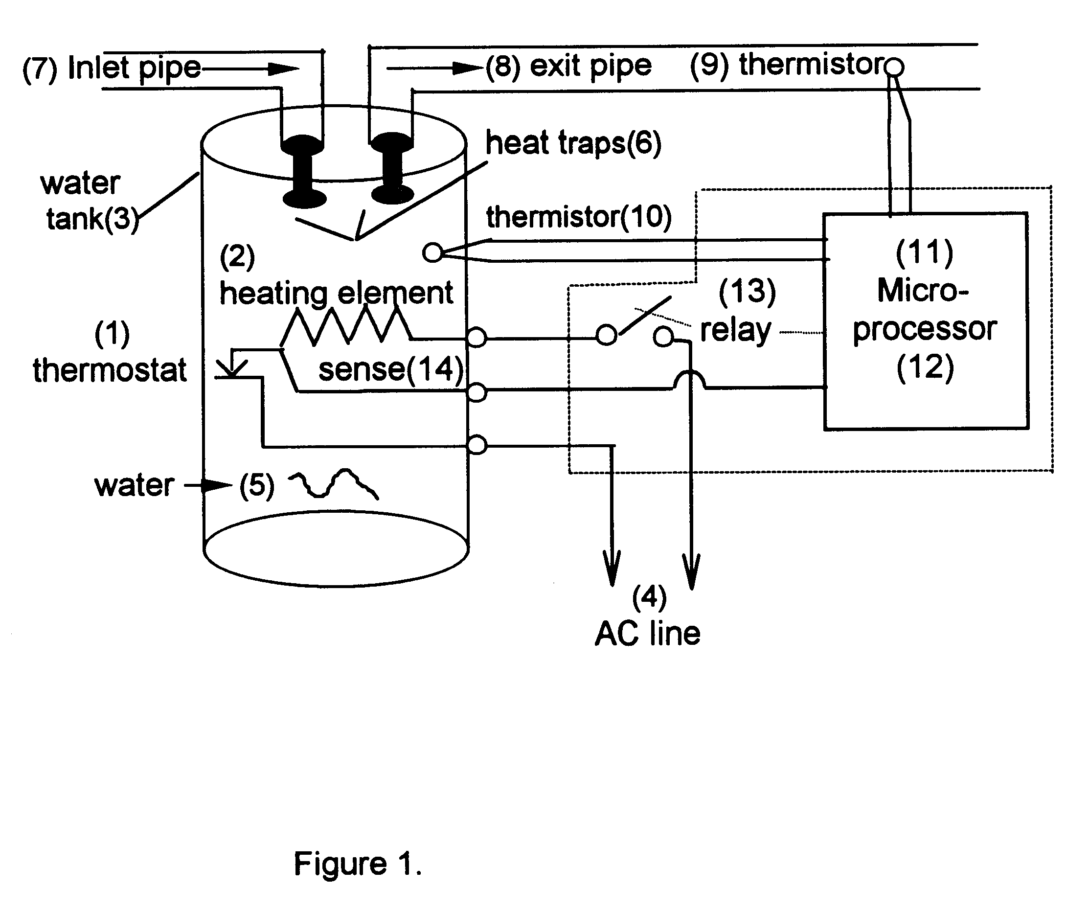
An electric hot water heater is typically provided with a prior art thermostatic control (1) and a prior art heating element (2) which heats water in a contained vessel (3), such as a cylindrical tank. An electric current (4) is allowed to flow through the heating element (2) by the thermostatic control (1) which is usually operated by a bi-metallic contact which closes when the temperature of the surrounding water (5) is below the thermostat's "set" temperature and which opens when the temperature of the surrounding water is above the thermostat's "set" temperature. Generally, such controls are subject to hysteresis which allows the water temperature to deviate from the set value by .+-.5.degree. F. or .+-.10.degree. F. Thermostat "set" temperatures are typically between 120.degree. F. and 180.degree. F. The modem water heater is often fitted with prior art "heat-trap" devices (6), such as an anti-flow valve fitted to an insulating plastic pipe, which provide a thermal barrier to ...


PUM

PropertyMeasurementUnit
temperaturesaaaaaaaaaa
temperatureaaaaaaaaaa

Abstract

A device and method is provided for automatically controlling the heating element(s) of an electric hot water heater to minimize electric energy consumption over a prolonged time period by projecting the future need for hot water based on it's use in prior time periods as well as by monitoring the use of hot water during current periods. The device saves energy by switching the heater "off" during times when the projected and current need for hot water is low or nonexistent thereby reducing the tank temperature and therefore energy losses to the ambient, while detecting the instantaneous requirement for hot water through utilization of a flow sensor arrangement, one of which is the utilization of thermistors on the exit pipe and on the tank or body of the heater. The device leaves all existing controls intact and may be adapted by end users to existing heaters or by manufacturers of original equipment (OEMs).

Description

1. Field of the InventionThis invention relates to residential and commercial electric hot water heaters of capacity up to thirty gallons and more specifically to a method for automatically determining when to turn on / off the electric current to such heaters so as to reduce the expenditure for electricity without compromising the users requirement for hot water.2. Description of the Related ArtAn electric hot water heater is illustrated in FIG. 1 and is typically provided with a thermostatic control (1) and a heating element (2) which heats water in a contained vessel (usually a cylindrical tank)(3). An electric current (4) is allowed to flow through the heating element by the thermostatic control which is usually operated by a bi-metallic contact which closes when the temperature of the surrounding water (5) is below the thermostat's "set" temperature and by opening when the temperature of the surrounding water is above the thermostats "set" temperature. Generally, such controls ar...

Claims


Application Information

Patent Timeline
Patent Type & Authority Patents(United States)
IPC IPC(8): F24H9/20G05D23/19
CPCG05D23/2422F24H9/2021G05D23/1917G05D23/24F24H15/414F24H15/176F24H15/219F24H15/37F24H15/156F24H15/172
Inventor STETTIN, DANIEL R.STERBER, FRANK W.
Owner STETTIN DANIEL R
Why Eureka
Try Eureka