Fractionation apparatus with low surface area grid above tray deck

a technology of surface area grid and filtering apparatus, which is applied in the direction of carburetor air, combustion-air/fuel-air treatment, and separation processes, etc., can solve the problem of unexpected increase in the vapor capacity of the filtering apparatus

Inactive Publication Date: 2001-09-25
UOP LLC
View PDF16 Cites 31 Cited by
  • Summary
  • Abstract
  • Description
  • Claims
  • Application Information

AI Technical Summary

Problems solved by technology

This results in the tray having an unexpectedly increased vapor capacity.

Method used


Image

  • Fractionation apparatus with low surface area grid above tray deck
  • Fractionation apparatus with low surface area grid above tray deck
  • Fractionation apparatus with low surface area grid above tray deck

Examples


Embodiment Construction

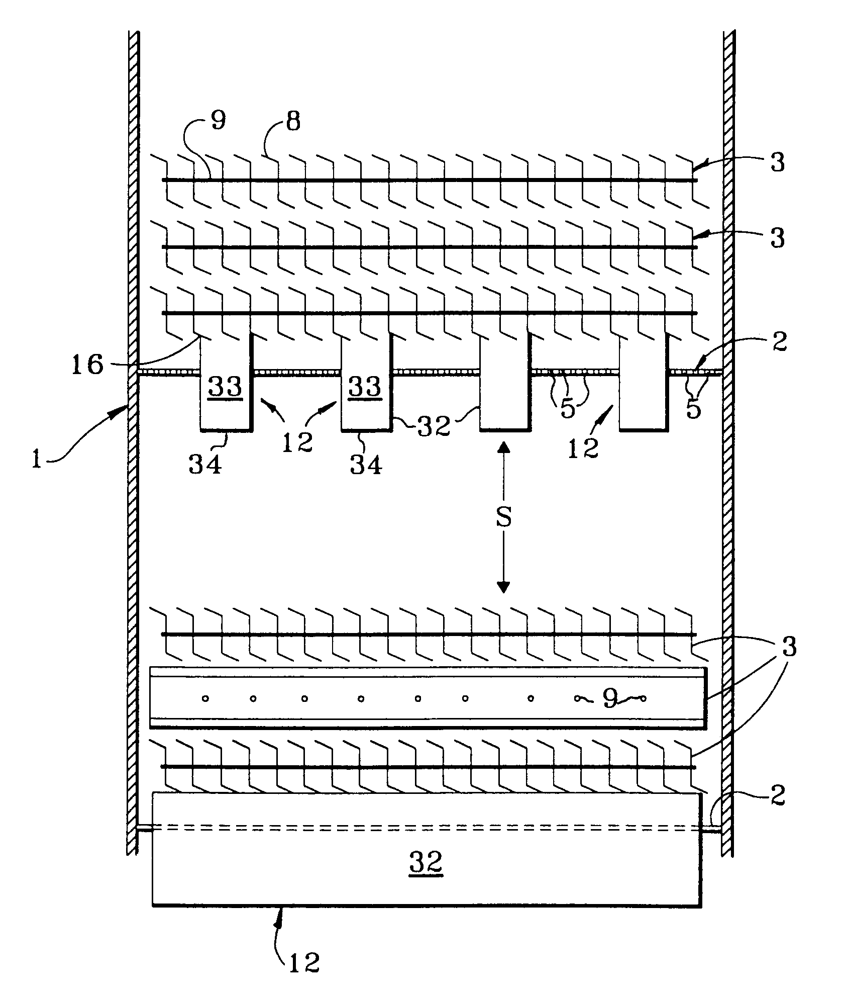
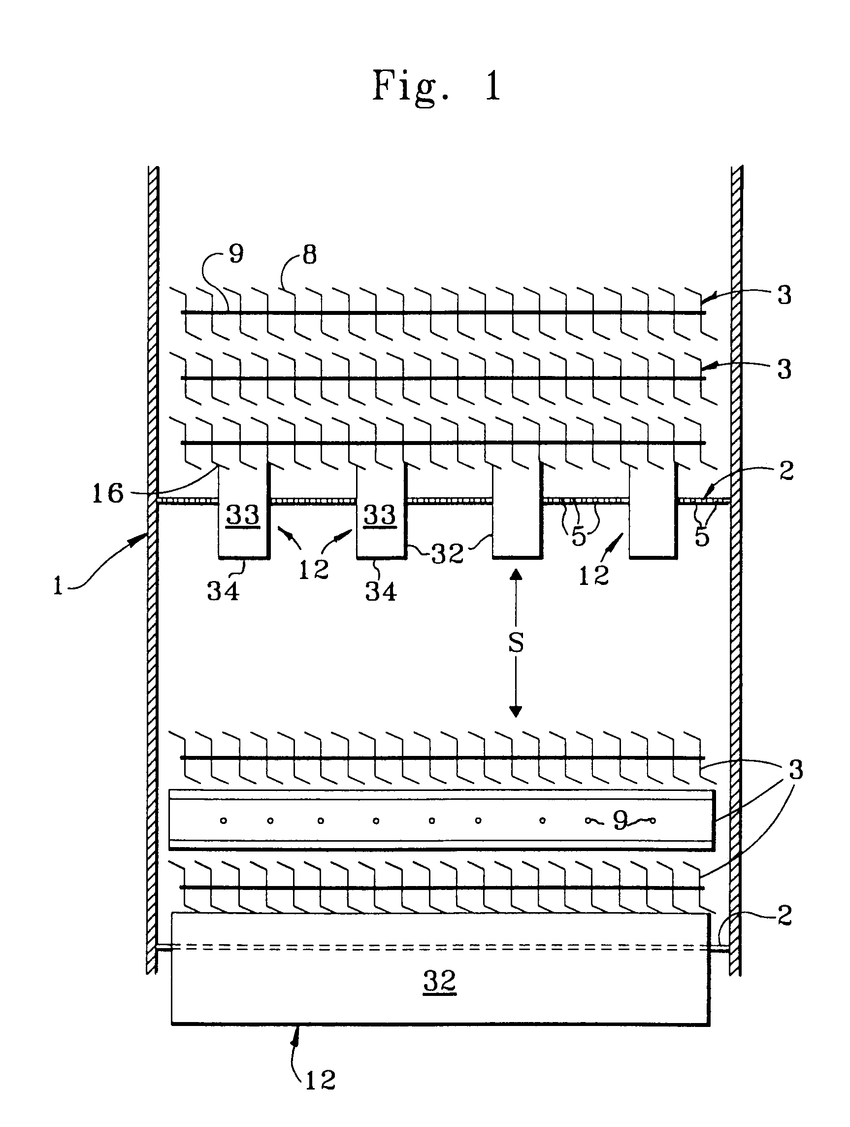
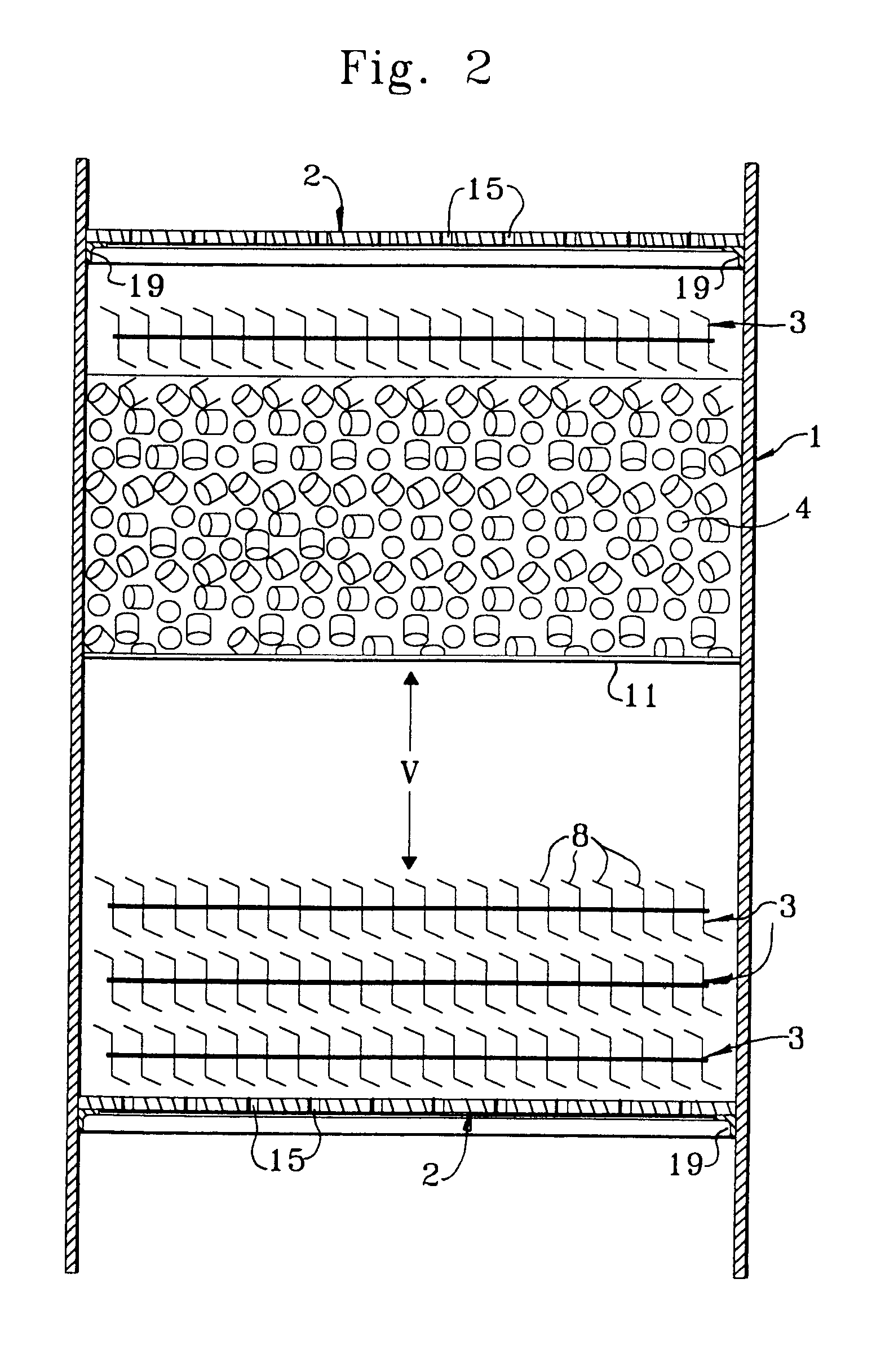
In a fractional distillation column a multicomponent feed stream is separated into an overhead vapor stream comprising a more volatile chemical compound and a bottoms liquid stream comprising a less volatile compound. That is, the compounds entering the column are separated therein, with the more volatile compound(s) being carried upward through the column by an ascending vapor stream. The vapor stream passes through the trays and eventually exits the column as an overhead vapor. A portion of the condensate derived from the overhead vapor is normally returned as liquid-phase reflux. The less volatile component(s) of the feed are concentrated into the descending liquid-phase stream and eventually removed from the bottom of the column. Heat and vapor are supplied to the bottom of the column by a reboiler as by vaporizing a portion of the bottoms liquid and returning it to the column.

Fractionation trays are employed within the column as a means of promoting vapor-liquid contacting and ...


PUM

PropertyMeasurementUnit
diametersaaaaaaaaaa
horizontal distancesaaaaaaaaaa

Abstract

The flooding capacity of a fractionation tray (2) is increased by the addition of at least one layer of low surface area grids (3) above the inlet to the downcomers (6,12) located on the tray (2). The grids (3) extend upward for a distance equal to one to four times the depth of the downcomers. The grids may rest upon the top edge of the downcomers or on the tray decking between the top portions of the downcomer sidewalls.

Description

The invention relates to gas-liquid contacting apparatus used primarily as fractionation trays for the separation of volatile chemical compounds in a fractional distillation column.Fractionation trays are widely used in the petrochemical and petroleum refining industries to promote the multistage vapor-liquid contacting performed in fractionation columns. The normal configuration of a fractionation column includes about 10 to 120 individual trays. Normally each tray is the same. The trays are mounted horizontally at uniform vertical distances referred to as the tray spacing of the column. This distance may vary within different parts of the column but is normally considered constant. Vapor generated at the bottom of the column rises through the tray which supports a quantity of liquid. The passage of the vapor through the liquid generates bubbles referred to as froth. The high surface area of the froth helps to quickly establish a compositional equilibrium between the vapor and liqu...

Claims


Application Information

Patent Timeline
Patent Type & Authority Patents(United States)
IPC IPC(8): B01D3/22B01D3/00B01D3/14B01D3/16B01D3/20
CPCB01D3/008B01D3/16B01D3/20B01D3/225B01D3/22B01J2219/32B01J2219/30
Inventor MONKELBAAN, DANIEL R.RESETARITS, MICHAEL R.MILLER, ROBERT J.
Owner UOP LLC
Why Eureka
Try Eureka