
Automatic exchanger for peritoneal dialysis

a technology of peritoneal dialysis and automatic exchanger, which is applied in the field of automatic exchanger apparatus for peritoneal dialysis, can solve the problems of installation fault or infection, contamination, and exchanger apparatus, and achieve the effects of avoiding operation errors, minimizing infection possibility, and facilitating operation

Inactive Publication Date: 2001-09-25
JMS CO LTD
View PDF5 Cites 134 Cited by
  • Summary
  • Abstract
  • Description
  • Claims
  • Application Information

AI Technical Summary

Benefits of technology

The exchanger apparatus for peritoneal dialysis fluids according to the present invention has the following advantages.(1) Since the connection and disconnection of tubes and the exchange of dialysis fluids including both fresh and waste are carried out in a sequence from start to finish, the troublesome task to the operator will be lessened with requiring no tormenting with the exchange procedure.(2) Since the exchange procedure is easily performed, malfunctions due to operational error or other possible troubles will be eliminated.(3) Since the manual task is minimized and the exchange action in the apparatus is isolated from the external conditions, the possibility of infection or contamination about the tube joints and their peripherals will be decreased.

Problems solved by technology

These known exchanger apparatuses are however disadvantageous in that the installation of tubes, connectors, and their shut-off members to the exchanger apparatuses has to be repeated twice before and after the delivery and drainage of dialysis fluids on patients.
Above all, the installation and its procedure is troublesome and may result in installation fault or infection (contamination).

Method used


Image

  • Automatic exchanger for peritoneal dialysis
  • Automatic exchanger for peritoneal dialysis
  • Automatic exchanger for peritoneal dialysis

Examples


Embodiment Construction

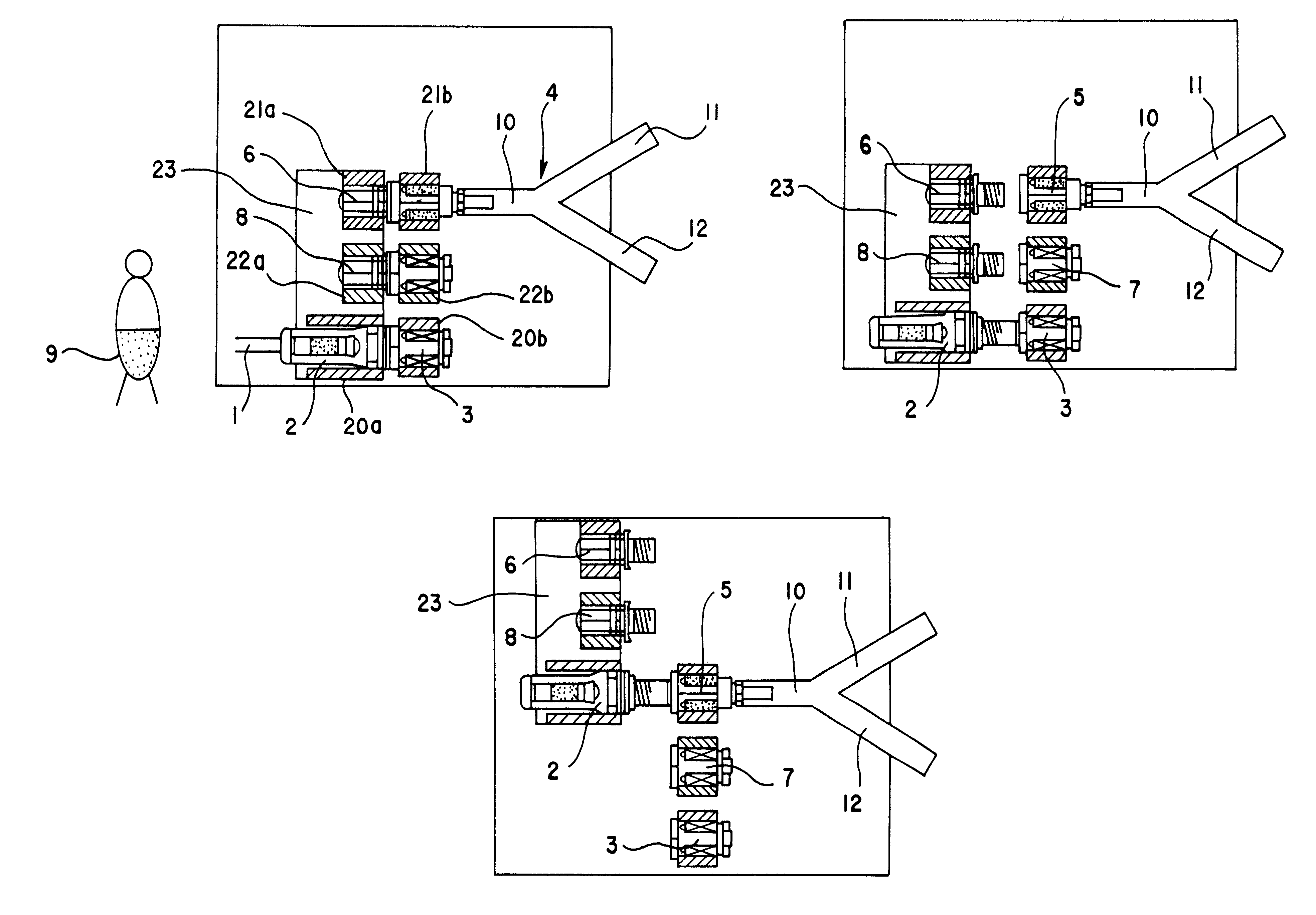
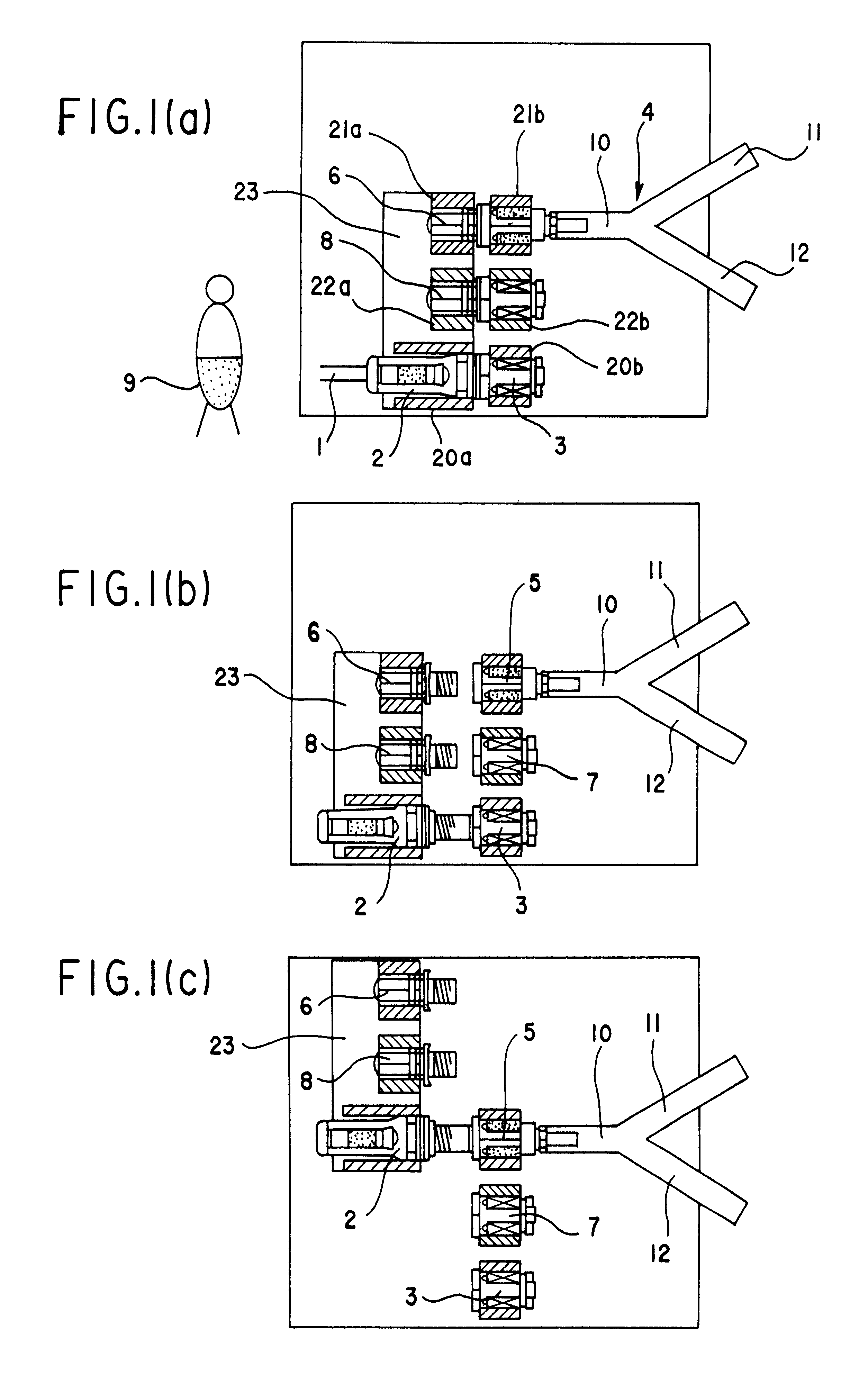
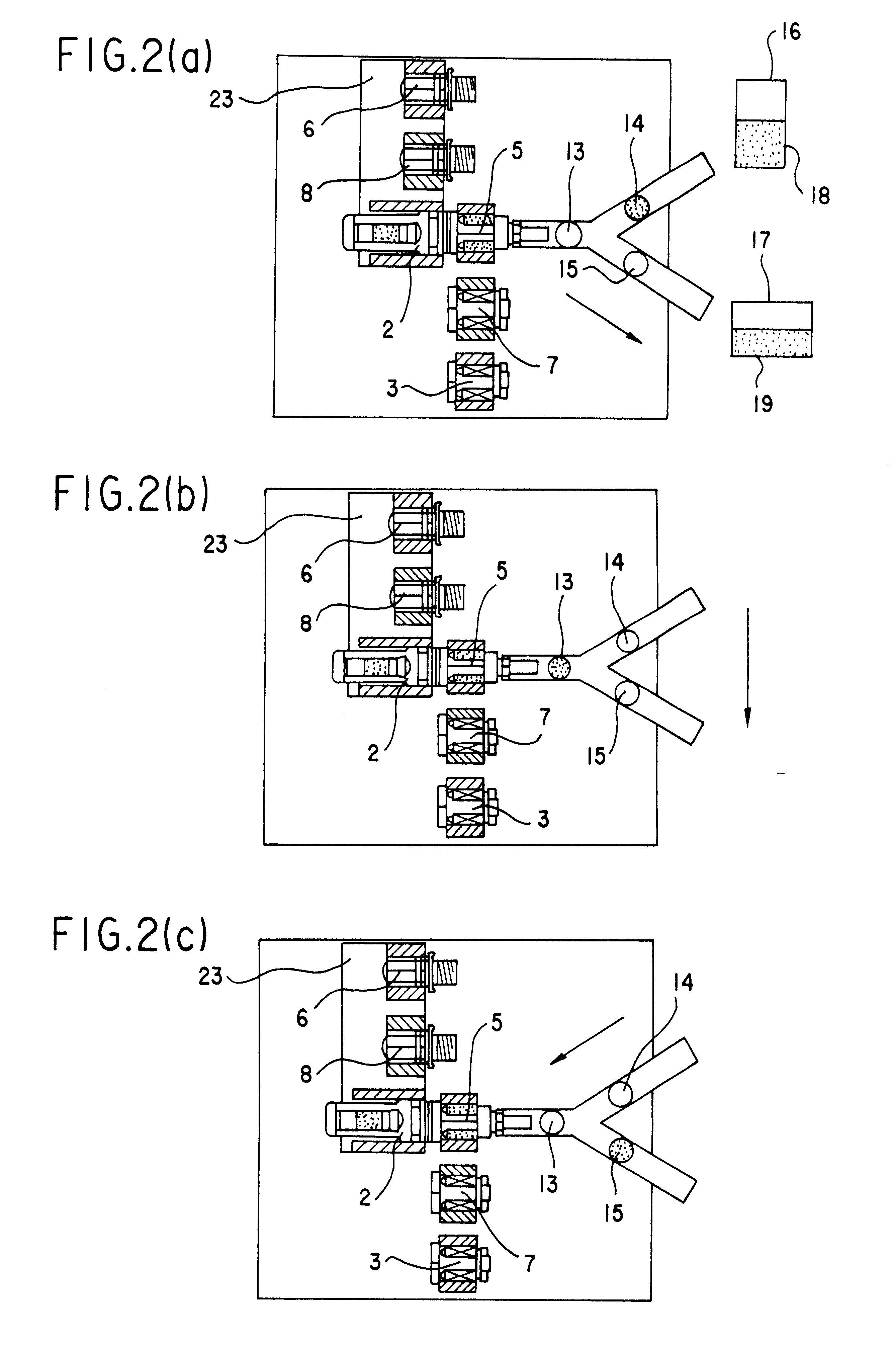
Referring to FIGS. 1 to 3, the procedure starts with (1) while the first holder 20 (comprising two segments 20a and 20b) is coupled with the patient side connector 2 in which the end of a tube 1 which is connected at the other end to a patient's peritoneal catheter is connected by threading to a shut-off member 3 (and which can also be connected by threading to the bag side connector 5 joined to the trunk of a Y-shaped tube 4), the second holder 21 (comprising two segments 21a and 21b) is coupled with the connector member 5 in which the end of the Y-shaped tube 4 is connected by threading to a shut-off member 6, and the third holder 22 (comprising two segments 22a and 22b) is coupled with a shut-off member 7 which can be connected to the patient side connector 2 upon completion of the filling the peritoneal cavity of the patient with a dialysis fluid supplied from a dialysis fluid bag (and is joined by threading to a sealing member 8), pressing a start button (not shown) for exchang...


PUM


Abstract

An automatic exchanger apparatus for peritoneal dialysis fluids is provided having a dialysis fluid bag and a drained fluid bag and arranged for connecting and disconnecting between the end of a peritoneal dialysis circuit equipped with a branching point and the end of a tube extending from a patient to drain the waste dialysis fluid from the cavity of the patient and fill the peritoneal cavity of the patient with a fresh peritoneal dialysis fluid for exchange, and in particular comprises: means A, B, and C for carrying out respectively a step (A) of connecting the end of the patient side tube to the end of the peritoneal dialysis circuit, a step (B) of delivering and draining the waste fluid, and a step (C) of, disconnecting the two ends and connecting the end of the patient side tube to its shut-off member, arranged for carrying out their respective steps (A) and (C) automatically; and a controlling means for controlling the respectively means to execute their respectively steps in a sequence. The apparatus is simple in the construction while carrying out, with much ease, the connection and disconnection of the tubes and the exchange of the fluids including a waste and a fresh supply one, hence avoiding operational errors of the operator and minimizing the possibility of infection and contamination.

Description

The present invention relates to an automatic exchanger apparatus for peritoneal dialysis fluids.An automatic exchanger apparatus for peritoneal dialysis fluids is provided in which the end of a tube connected to a peritoneal cavity of a patient is connected to and disconnected from the end of a tube in a peritoneal dialysis circuit, which is connected at the other end to a dialysis fluid bag or the like, to exchange automatically or semi-automatically (using manual procedures) the dialysis fluid. The apparatus was developed for the purpose of easing a troublesome, manual process of exchanging the fluids with the use of a mechanical system.Some of such known automatic exchanger apparatuses are disclosed in examined publication of Tokkou Hei. 3-52986 and Tokkou Hei. 2-27936 and Japanese unexamined Patent Publication. Tokkai Hei. 8-725.They are mainly classified connector-changeable type, tubing fuse-bond type and sterilizing means equipped type.These known exchanger apparatuses are h...

Claims


Application Information

Patent Timeline
Patent Type & Authority Patents(United States)
IPC IPC(8): A61M1/28A61M39/10A61M39/00
CPCA61M1/28A61M1/288A61M39/10
Inventor SHINMOTO, KAZUHIROTANAKA, SEISHINFUJII, JUNYA
Owner JMS CO LTD
Learn More