Antenna unit and communication device using the same
What is Al technical title?
Al technical title is built by PatSnap Al team. It summarizes the technical point description of the patent document.
a communication device and antenna technology, applied in the direction of resonant antennas, resonant antennas, resonant antennas, etc., can solve the problem of difficulty in realizing a broader bandwidth
Inactive Publication Date: 2001-10-09
MURATA MFG CO LTD
View PDF7 Cites 64 Cited by
Summary
Abstract
Description
Claims
Application Information
AI Technical Summary
This helps you quickly interpret patents by identifying the three key elements:
Problems solved by technology
Method used
Benefits of technology
Furthermore, by providing a plurality of control electrodes and switches respectively connected thereto, and by turning on and off each of the switches, it is possible to establish a much broader bandwidth.
Furthermore, in a communication device according to the present invention, because an antenna unit where frequencies can be changed is provided, it is possible to establish a broader bandwidth.
Problems solved by technology
However, in the conventional antenna unit 101, frequencies of the single antenna unit 100 are to be switched over and it is difficult to realize broader bandwidth.
Method used
Image
Click on the blue label to locate the original text in one second.
Reading with bidirectional positioning of images and text.
Examples
first embodiment
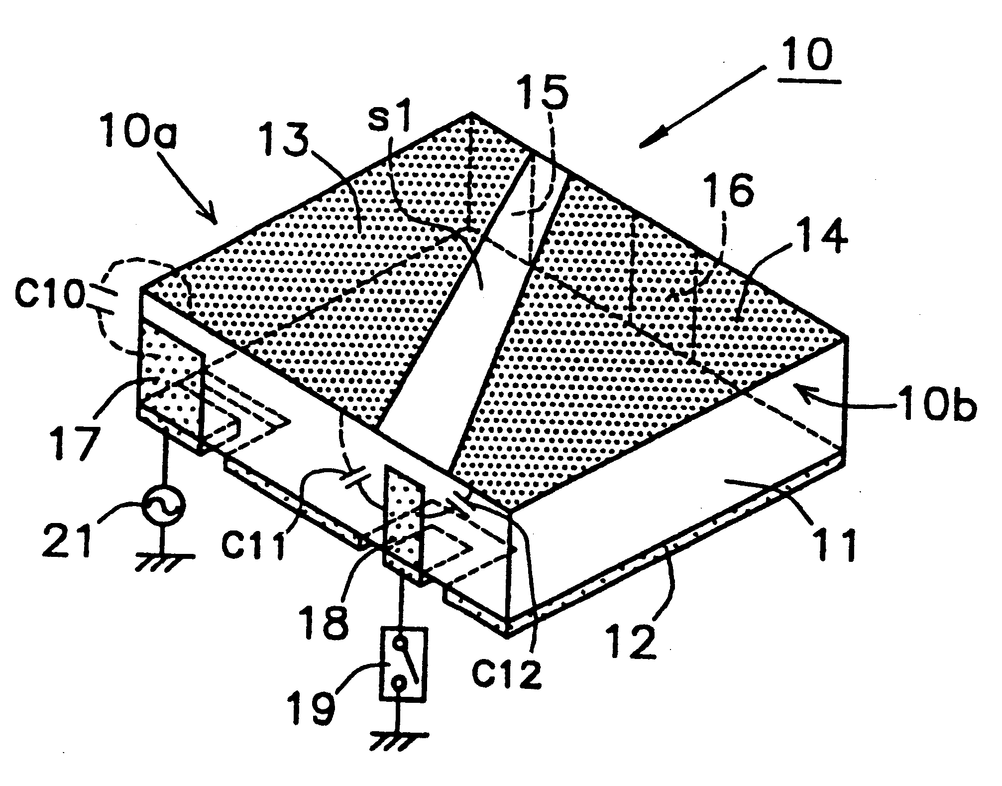
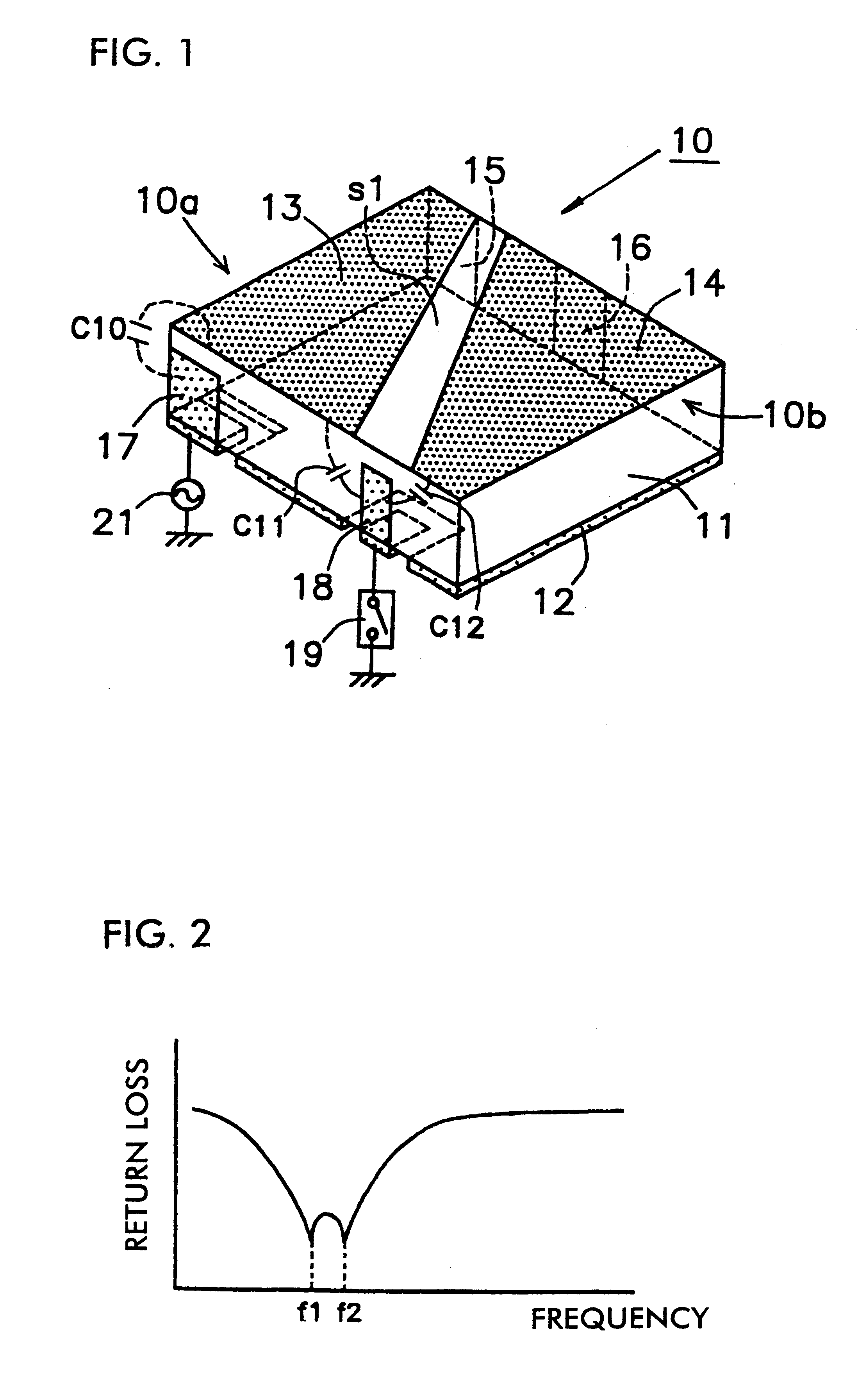
The construction of an antenna unit according to the present invention will be described with reference to FIG. 1.
In the drawing, an antenna unit 10 is made up of a basic body 11 of a dielectric material such as ceramic, resin, etc., which comprises a grounding electrode 12, a first microstrip antenna 10a as a first antenna, and a second microstrip antenna 10b as a second antenna.
Out of these, the grounding electrode 12, is formed on one main surface of the basic body 11. Furthermore, the first microstrip antenna 10a comprises a first radiation electrode 13 formed on the other main surface of the basic body 11. Furthermore, the second microstrip antenna 10b comprises a second radiation electrode 14 formed on the other main surface of the basic body 11.
The first and second radiation electrodes 13 and 14 are formed so as to face each other through a slit s1. This slit s1 is formed so that the width on the side of one end may be narrower than the width on the side of the other end and ...
second embodiment
Next, the construction of an antenna unit according to the present invention is described with reference to FIG. 6.
In the drawing, an antenna unit 30 comprises a first microstrip antenna 32 as a first antenna and a second microstrip antenna 33 as a second antenna which are formed on a basic body 31 of a rectangular solid made of dielectric material such as ceramic, resin, etc.
Here, on nearly all of one main surface of the basic body 31, a grounding electrode 34 is formed. Furthermore, a first radiation electrode 32a constituting the first microstrip antenna 32 and a second radiation electrode 33a constituting the second microstrip antenna 33 which are parallel to each other, are formed so as to be in contact with a pair of sides, opposed to each other, of the other main surface of the basic body 31, respectively. Furthermore, each one end of the first and second radiation electrode 32a and 33a is formed so as to be open circuited and each of the other ends is connected to the ground...
PUM
Abstract
In an antenna unit, the generation of capacitances between each of the open ends of first and second microstrip antennas and a control electrode is controlled by turning a switch on and off, both antenna frequencies being simultaneously changed. The antenna unit has a basic body having first and second main surfaces and at least one end surface extending between the main surfaces; a grounding electrode provided on the first main surface of the basic body; a first radiation electrode forming a first antenna, having an open end at one end thereof, and provided on the second main surface of the basic body; a second radiation electrode forming a second antenna, having an open end at one end thereof, and provided on the second main surface of the basic body; a first connecting electrode for connecting the first radiation electrode to the grounding electrode, and provided on an end surface of the basic body; a second connecting electrode for connecting the second radiation electrode to the grounding electrode, and provided on an end surface of the basic body; a feeding electrode for transmitting a signal to at least one of the first radiation electrode and the second radiation electrode, and provided on the basic body; and a control electrode on the basic body for providing coupling capacitances between the open end of the first radiation electrode and the control electrode and between the open end of the second radiation electrode and the control electrode, and provided so as to be close to each of the open ends.
Description
1. Field of the InventionThe present invention relates to an antenna unit in which double resonance is realized by using two antennas and in which it is possible to simultaneously change both frequencies. The present invention also relates to a communication device using the antenna unit.2. Description of the Related ArtAmong conventional antenna units, the antenna unit which has been disclosed in Japanese Unexamined Patent Application Publication No. 11-136025 (Japanese Patent Application No. 10-204902) is taken as an example and described with reference to FIG. 8.In the drawing, an antenna unit 101 is shown. The unit 101 includes a switch 109 is coupled to an antenna 100. The antenna 100 comprises a grounding electrode 103, a radiation electrode 104, a feeding electrode 106, and a control electrode 108 provided on the surface of a basic body 102 made of a dielectric material. One end of the radiation electrode 104 is open circuited. Furthermore, the feeding electrode 106 is formed...
Claims
Application Information
Patent Timeline
Application Date:The date an application was filed.
Publication Date:The date a patent or application was officially published.
First Publication Date:The earliest publication date of a patent with the same application number.
Issue Date:Publication date of the patent grant document.
PCT Entry Date:The Entry date of PCT National Phase.
Estimated Expiry Date:The statutory expiry date of a patent right according to the Patent Law, and it is the longest term of protection that the patent right can achieve without the termination of the patent right due to other reasons(Term extension factor has been taken into account ).
Invalid Date:Actual expiry date is based on effective date or publication date of legal transaction data of invalid patent.