Machine tool locator

a technology of tool locator and tool body, which is applied in the direction of manufacturing tools, instruments, metal-working machine components, etc., can solve the problems of stiction, dirt and wear, and the inability of touch probe systems to provide useful visual feedback, and achieve accurate measurement and positioning. , the effect of small tolerances

Inactive Publication Date: 2001-10-09
LOS ALAMOS NATIONAL SECURITY
View PDF15 Cites 37 Cited by
  • Summary
  • Abstract
  • Description
  • Claims
  • Application Information

AI Technical Summary

Benefits of technology

To achieve the foregoing and other objects, and in accordance with the purposes of the present invention, as embodied and broadly described herein, there has been i

Problems solved by technology

Touch probe systems cannot provide visual feedback useful for measuring the shape of the cutting tool

Method used


Image

  • Machine tool locator
  • Machine tool locator
  • Machine tool locator

Examples


example i

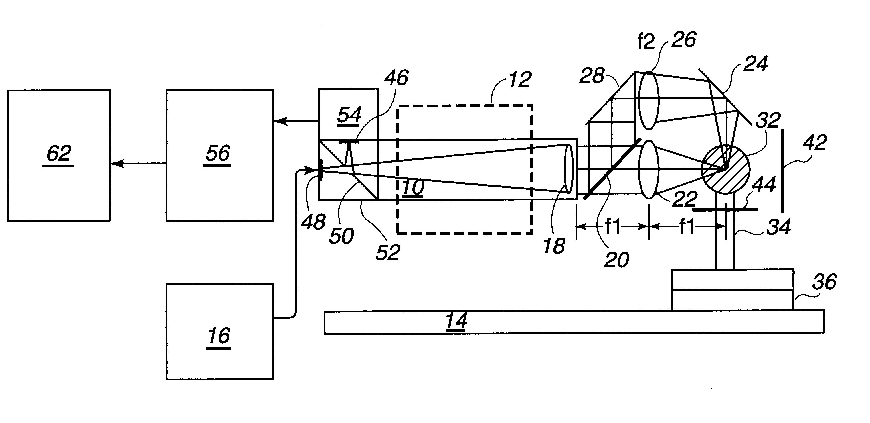
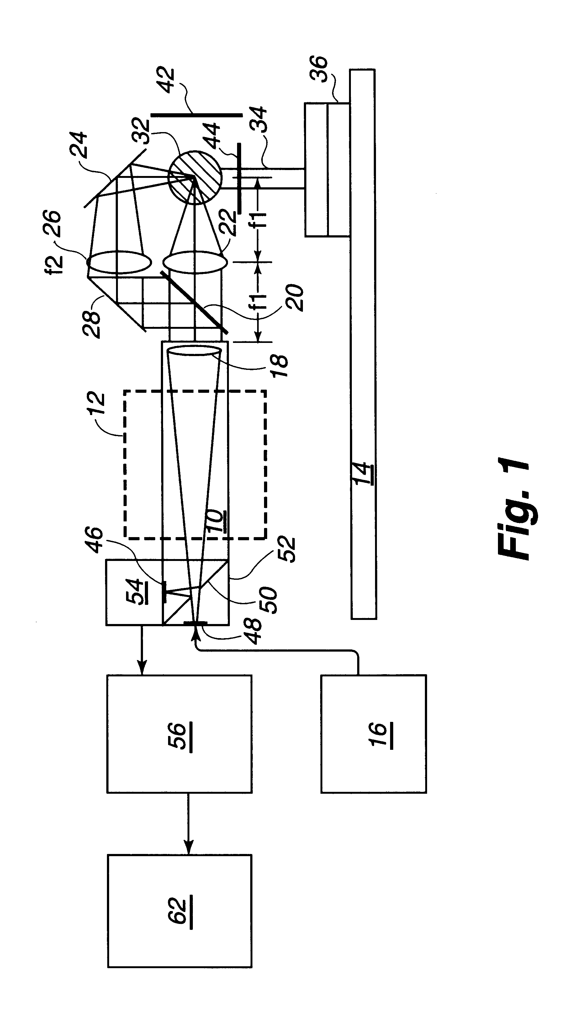
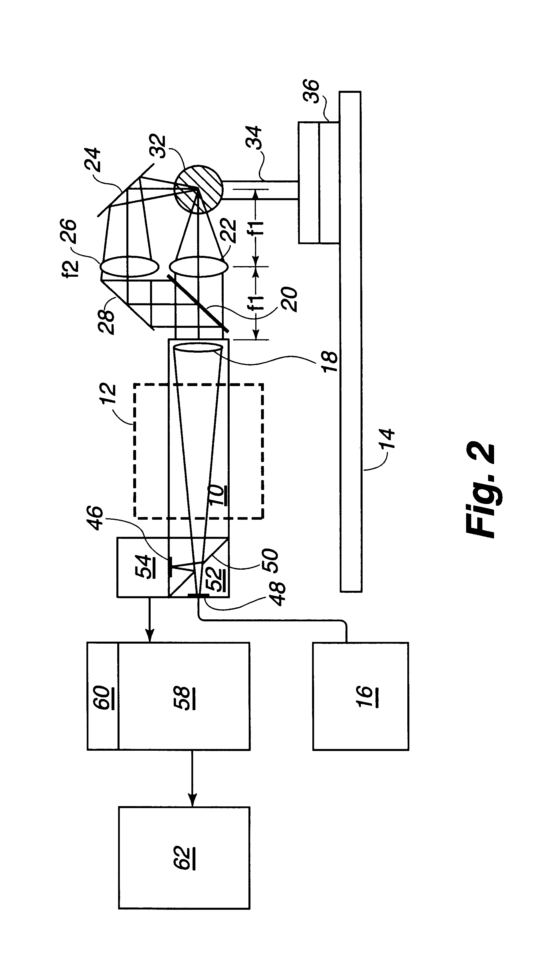
An algorithm for calculating the sensitivity of the invention apparatus was determined. When the invention apparatus is set up as shown in FIG. 1, if the reference tooling ball is moved by distance .epsilon..sub.1, the image of the autocollimated return on the CCD camera moves by .epsilon..sub.2 =(f.sub.ccd divided by f.sub.ball) (M.alpha.) 2.epsilon..sub.c, where f.sub.ccd is the focal length of the lens on the CCD side and f.sub.ball is the focal length of the lens on the ball side; M.alpha. is the angular magnification of the autocollimator. The quantity 2(f.sub.ccd divided by f.sub.ball) (M.alpha.) is the effective magnification and will typically be in the range from about 5 to about 20, depending upon design choices. If a nominal value for the overall magnification of 10 is taken, a 40 microinch error in ball positioning causes a 400 microinch displacement on the CCD. With electronic magnification (CCD to display monitor, which is typically 20 to 50) several microns of ball di...

example ii

For a laboratory measurement of the sensitivity of the invention apparatus, equipment was set up essentially in the manner shown in FIG. 1. The sensitivity for positioning a reference tooling ball on the straight through axis was tested by changing the relative position of the alignment telescope and the tooling ball with micrometers. A 10-inch monitor was used.

For the straight through path, i.e., the axis used to set tool height, and using a 60 mm lens, the autocollimated return moved 5 divisions when the micrometer was adjusted by 0.0035 inches. The sensitivity for this axis is therefore 0.0007 inches / division. With this sensitivity, it is quite easy to repeat alignment settings on the tooling ball to .+-.0.000010 inches.

This magnification seemed to be about the right trade off between field of view and mechanical adjustment, although a little more magnification would be preferred if there were room enough between the optical locator device and the machine tool.

example iii

The sensitivity for positioning a reference tooling ball on the long axis was tested by changing the relative position of the alignment telescope and the tooling ball with micrometers. A 120 mm lens was put into a translation mount that was used for alignment. The translation mount was put in the long leg of the upper path to keep the head compact for the best mechanical stability.

The sensitivity measured for this axis was 0.0053 inches / 5 divisions or 0.001 inch / division. The ratio of the magnifications (10 / 7) was not quite the same as the ratio of the lens focal length (10 / 6). This was most likely because the alignment telescope focus was not exactly set for infinity, but rather adjusted to get both axes into the best focus as the same time. Even though the sensitivity for this axis was less than that for the straight through axis in Example II, it was possible to repeat alignments to the tooling ball to .+-.0.000020 inches.


PUM


Abstract

Machine tools can be accurately measured and positioned on manufacturing machines within very small tolerances by use of an autocollimator on a 3-axis mount on a manufacturing machine and positioned so as to focus on a reference tooling ball or a machine tool, a digital camera connected to the viewing end of the autocollimator, and a marker and measure generator for receiving digital images from the camera, then displaying or measuring distances between the projection reticle and the reference reticle on the monitoring screen, and relating the distances to the actual position of the autocollimator relative to the reference tooling ball. The images and measurements are used to set the position of the machine tool and to measure the size and shape of the machine tool tip, and examine cutting edge wear. patent

Description

This invention relates to an optical machine tool locator and a method of locating a machine tool.It is necessary to know the machine tool tip radius and the position of the machine tool edge relative to the manufacturing machine axis to accurately machine parts within close tolerances. Presently this is generally done using electronic touch probes which locate the tool at the machine in only two dimensions. Touch probe systems cannot provide visual feedback useful for measuring the shape of the cutting tool edge and detecting tool wear and condition. Touch probes are also subject to stiction, dirt and wear.Visual systems such as optical comparators have been used to measure the shape of the machine tool cutting edge or to detect cutting tool wear. Generally these visual systems are remote from the manufacturing machine and thus are not aligned to reference points that have precise relationships to the machine axes.Therefore, there is still a need for a measuring and positioning sys...

Claims


Application Information

Patent Timeline
IPC IPC(8): B23Q17/22B23Q17/09B23Q17/24
CPCB23Q17/09B23Q17/22B23Q17/24B23Q17/0909B23Q17/0957
Inventor HANLON, JOHN A.GILL, TIMOTHY J.
Owner LOS ALAMOS NATIONAL SECURITY
Why Eureka
Try Eureka