Stock inlet

a stock inlet and stock technology, applied in the field of stock inlet, can solve the problems of poor formation and low jet quality

Inactive Publication Date: 2001-10-16
VOITH PATENT GMBH
View PDF7 Cites 1 Cited by
  • Summary
  • Abstract
  • Description
  • Claims
  • Application Information

AI Technical Summary

Benefits of technology

A high strength as well as a high jet stability and favorable formation are achieved simultaneously as a result of this embodiment. The disadvantages previously associated with angular momentum generators are consequently eliminated. Moreover, the striped structure (tiger stripes) in the paper are prevented or at least mitigated.
It is advantageous if at least one yoke or insert is designed for a pressure-induced influence of the applicable partial suspension flow and preferably includes at least one pressure impulse generating element. In this connection, each tubular element or tubular insert can be associated with, for example, at least two and preferably two to twelve pressure impulse generating elements.
In certain instances, it can also be advantageous for at least one pressure impulse generating element to be provided that is constituted by an electromagnetic element.
It is also advantageous if at least one tubular insert is provided which can be inserted into the diffusor block in order to receive stock suspension from a distributor.
In addition, it is advantageous if the intersection points A and B are disposed on a line with the radius center point M of the arc of the ends of the dividing element. There is also the advantageous possibility of allowing the intersection points A and B to coincide with the radius center point M of the arc of the ends of the dividing element.

Problems solved by technology

A problem of these known stock inlets lies in the fact that the paper produced therewith has a striped structure, known as "tiger stripes," running the width of the machine, whose origin has not yet been definitively explained.
A disadvantage of such an angular momentum generator, however, is the low jet quality and poor formation.
The at least one magnet ring may act on the at least two blade, thereby generating a turbulence.

Method used


Image

  • Stock inlet
  • Stock inlet
  • Stock inlet

Examples


Embodiment Construction

The particulars shown herein are by way of example and for purposes of illustrative discussion of the embodiments of the present invention only and are presented in the cause of providing what is believed to be the most useful and readily understood description of the principles and conceptual aspects of the present invention. In this regard, no attempt is made to show structural details of the present invention in more detail than is necessary for the fundamental understanding of the present invention, the description taken with the drawings making apparent to those skilled in the art how the several forms of the present invention may be embodied in practice,

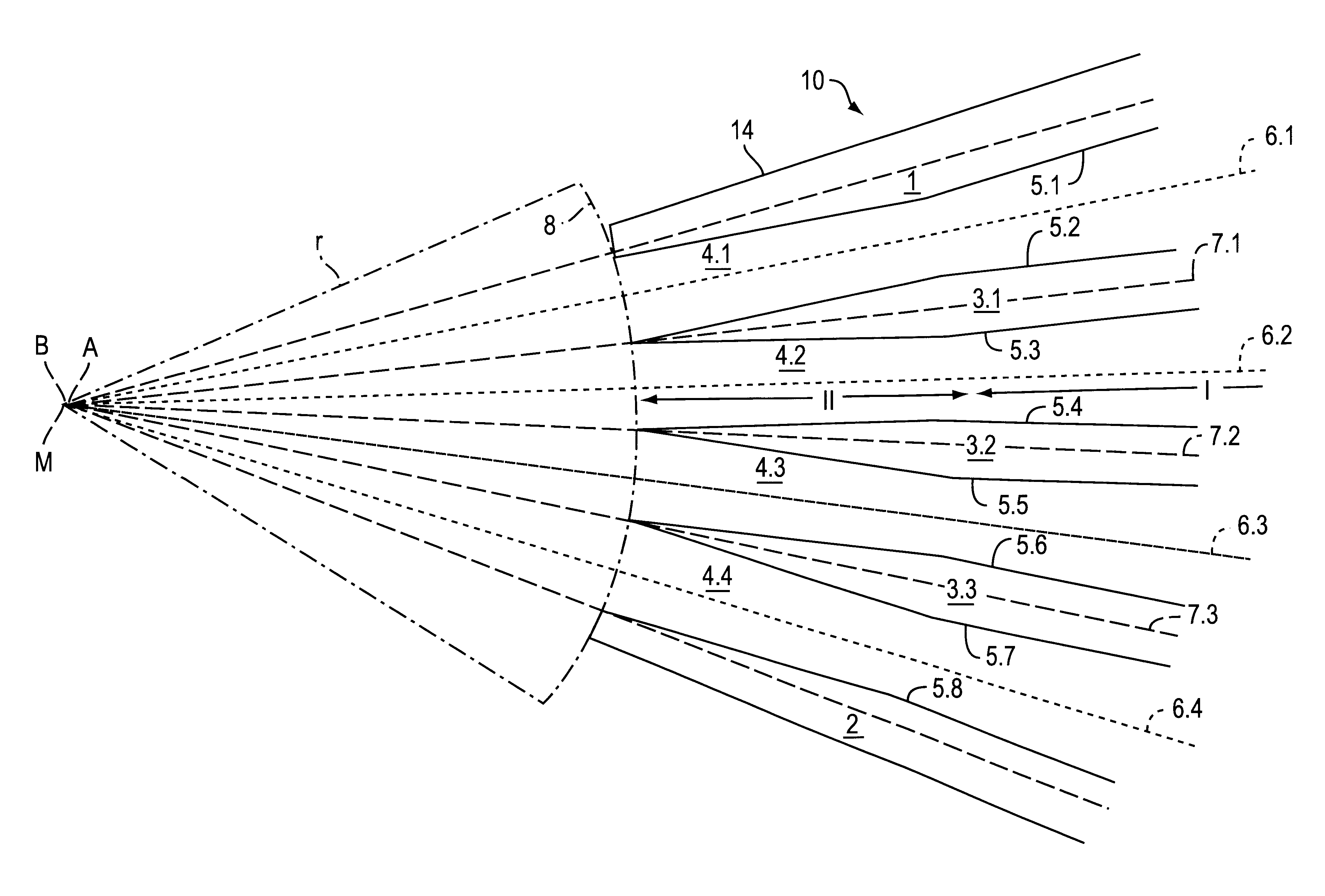
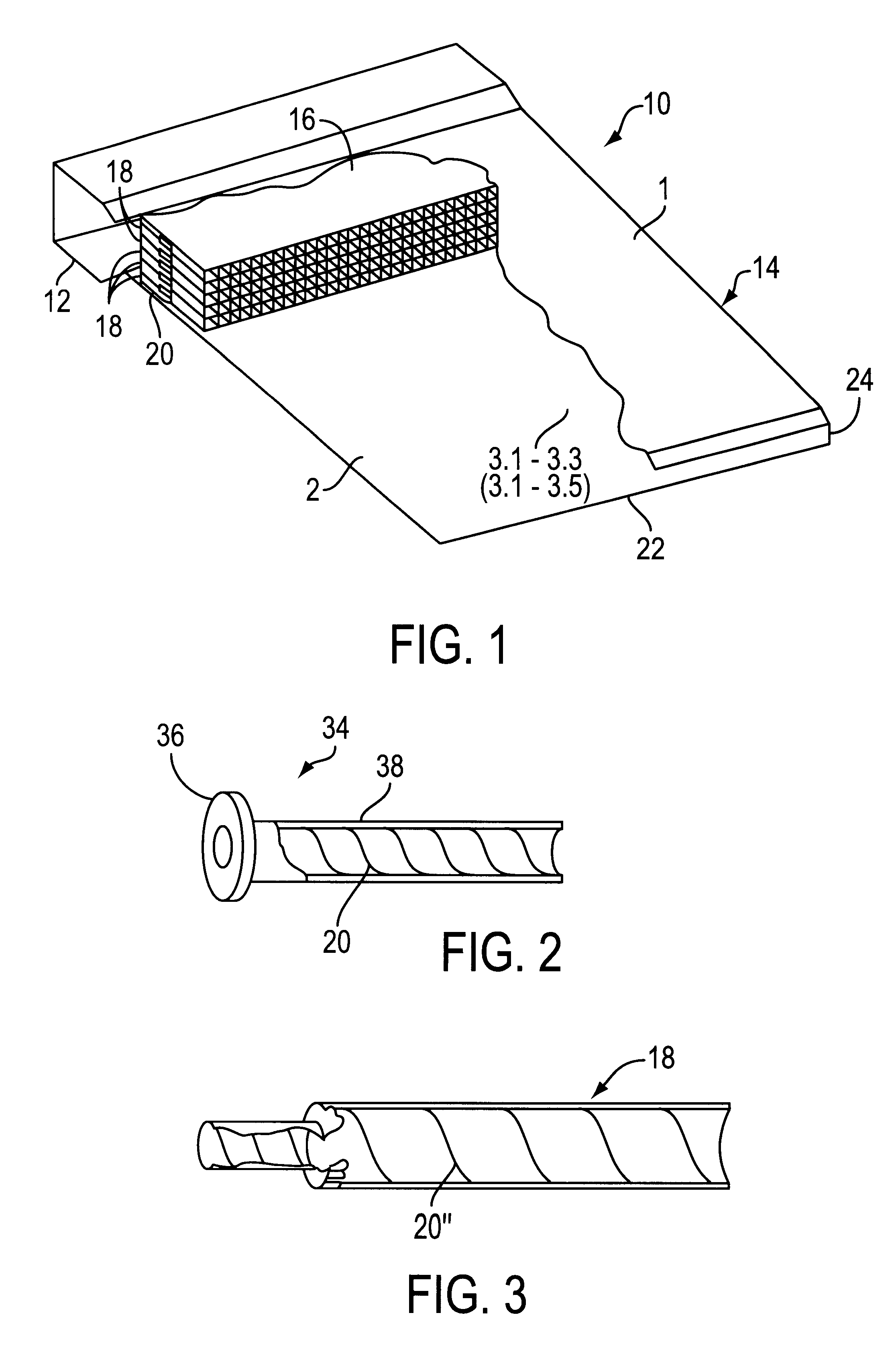
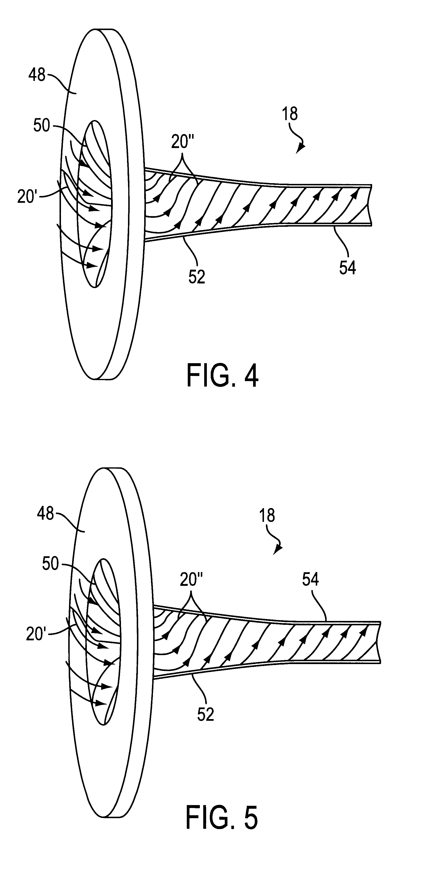
In a purely schematic form, FIGS. 1 to 18 depict a stock inlet 10 whose diffusor block 16, which contains a number of tubular elements 18 or whose turbulence generator, which is provided with a turbulence generating element 20 (e.g., see FIG. 1) and whose stock inlet aperture 14 is provided with dividing elements 3.1 to 3.5 in ...


PUM


Abstract

Stock inlet of a paper machine that includes at least one stock suspension supply, a diffusor block having a plurality of tubular elements, dividing elements which extend across a width of the machine, and a stock inlet aperture having a top wall and a bottom wall. The dividing elements are located between the top wall and the bottom wall, so that a plurality of suspension conduits are formed, which extend across the width of the machine. Further, the stock inlet aperture is positioned one of adjacent one wire and between two wires. The suspension conduits include a first region and a second region disposed downstream of the first region, with respect to a stock flow direction. The first region is formed by flat boundary surfaces which extend across the width of the machine and converge in the stock flow direction, and each of the dividing elements has a sharper convergence of surfaces in the second region than in the first region. The plurality of tubular elements are associated with a turbulence generating element to produce secondary turbulence currents in partial suspension flows conveyed through the plurality of tubular elements. In this way, the secondary turbulence currents overlap a primary current of each partial suspension flow, and all of the dividing elements have a contour and an arrangement so that the second region for each suspension conduit is of equal length and has an identical cross sectional course.

Description

The present application claims priority under 35 U.S.C. .sctn. 119 of German Patent Application No. 199 36 330.7, filed on Aug. 2, 1999, the disclosure of which is expressly incorporated by reference herein in its entirety.1. Field of the InventionThe invention relates to a stock inlet, in particular a multi-layer stock inlet, of a paper machine having at least one stock suspension supply, a diffusor block with a multitude of tubular elements, and a stock inlet aperture which has a number of suspension conduits running the width of the machine, which are formed between a top and bottom wall of the stock inlet aperture by at least two, preferably three, dividing elements which run the width of the machine and through which the stock suspension is conveyed onto a wire or between two wires, with the suspension conduits having a first region I and a second region II disposed downstream, with the first region I being constituted by flat boundary surfaces, which run the width of the machi...

Claims


Application Information

Patent Timeline
Patent Type & Authority Patents(United States)
IPC IPC(8): D21F1/02
CPCD21F1/02D21F1/026D21F1/028
Inventor RUF, WOLFGANGHOLZER, WALTER
Owner VOITH PATENT GMBH
Why Eureka
Try Eureka