Multiple coupled resonant loop antenna

a resonant loop and coupled technology, applied in the direction of antennas, antenna adaptation in movable bodies, electrical equipment, etc., can solve the problems of high reactive impedance of the antenna at the loop terminal, the low profile of the antenna, and the inability to be low above the conductive plan

Inactive Publication Date: 2001-10-16
MOBILE KNOWLEDGE
View PDF6 Cites 24 Cited by
  • Summary
  • Abstract
  • Description
  • Claims
  • Application Information

AI Technical Summary

Problems solved by technology

However, such antennas are not low profile, as they must be mounted with their axes perpendicular to a conductive ground plane.
Dipoles have balanced elements each 1/4 wavelength long, but cannot be low profile above and in close proximity to a conductive plane.
In general, the impedance of the antenna at the loop terminals is undesirably highly reactive resulting from the series of a very small resistance value and a high value inductance.
The inductive loop can be resonated with a capacitor 9, but this results in an equally undesirable very high output impedance.
However, such a loop also has a considerable parasitic resistance arising from the well known skin effect and the equivalent series resistance (ESR) of capacitors used to transform the output impedance.
Currents flowing in this strip would require greater energy than at the edges, and consequently the current becomes non-uniform, thereby

Method used


Image

  • Multiple coupled resonant loop antenna
  • Multiple coupled resonant loop antenna
  • Multiple coupled resonant loop antenna

Examples


Embodiment Construction

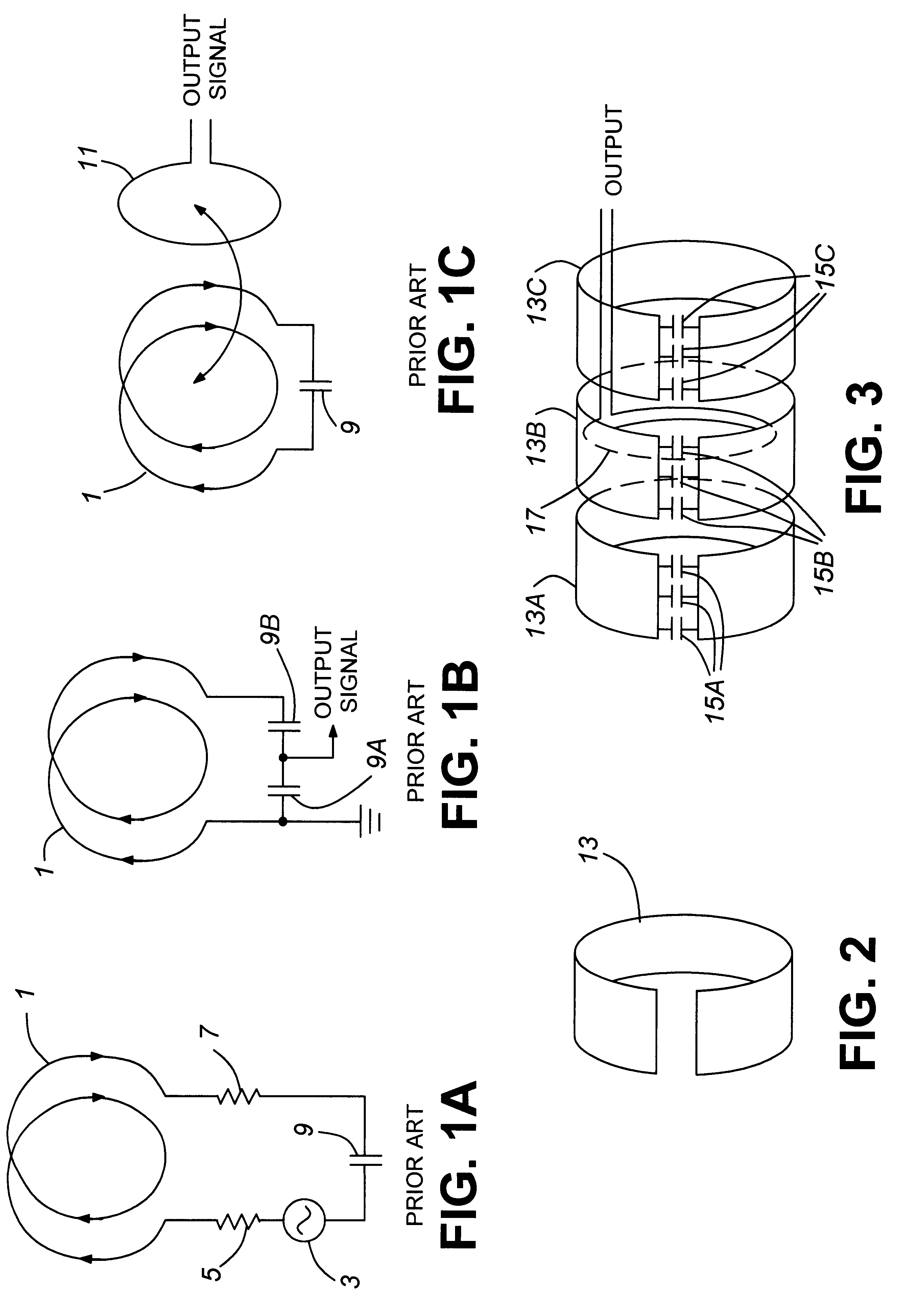
The present invention is comprised of a predetermined number n co-linear wire or metal strip loops, each tuned with a capacitor. The individual loops are tightly coupled e.g. through mutual inductance.

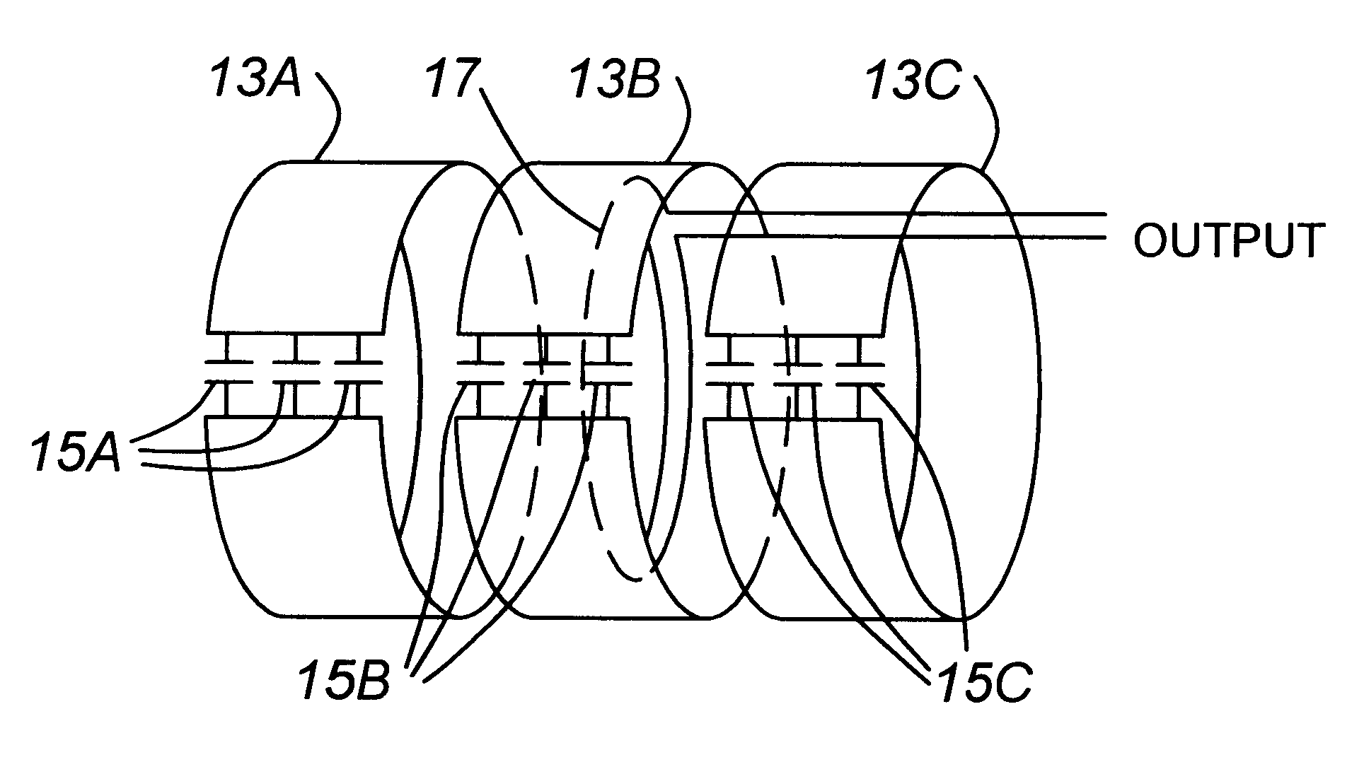
In a preferred embodiment, as, shown in FIG. 3, loops 13A, 13B and 13C are constructed of copper strip in a circular (as shown, each similar to strip 13 of FIG. 2) or elliptical or rectangular cross sectional form. An output feed is taken from an additional loop 17 which is loosely coupled to the tightly coupled group of loops 13A-13C. The coupling is arranged so as to provide a matched feed to a transceiver element (not shown) to which the output of the loosely coupled loop 17 is coupled. At least one, but preferably more than one capacitor 15A, 15B and 15C is coupled to ends of the respective loops 13A, 13B and 13C.

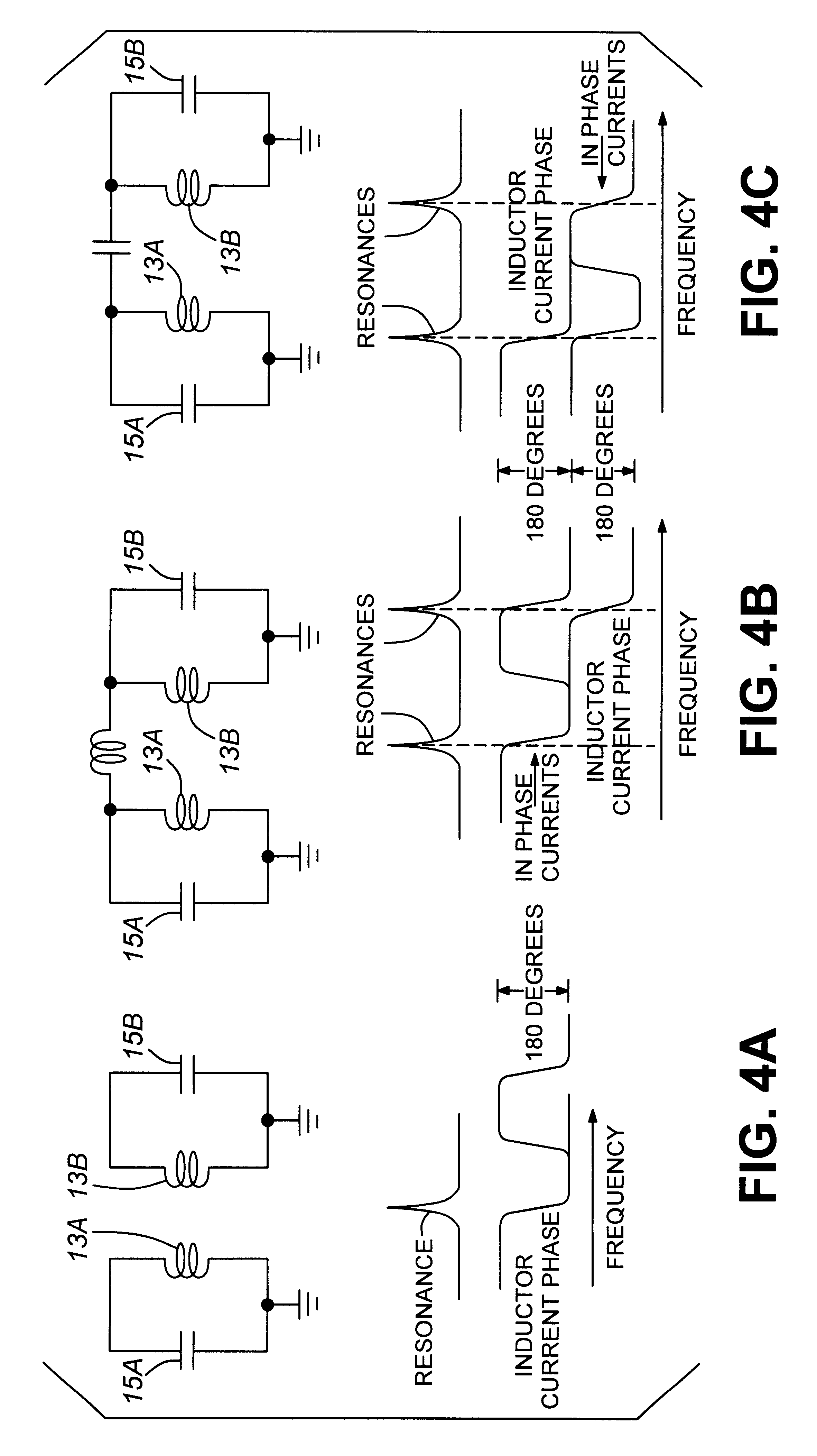
Each loop, and group of capacitors or single capacitor sets, form a resonator (or tank), the resonant frequency of which can be changed by varying the capacitance of the a...


PUM


Abstract

A loop antenna which is electrically small relative to a wavelength of a signal which it is designed to receive. The antenna is an electrically small, low profile, band switchable antenna which can be mounted on a metallic surface such as a truck or railway car rooftop and can be used to communicate with earth satellites. The antenna is polarized such that the plane containing the electric field is horizontal. Alternatively, the antenna can receive circularly polarized signals.

Description

This invention relates to the field of antennas and in particular to a loop antenna which is electrically small relative to a wavelength of a signal which it is designed to receive or transmit.BACKGROUND TO THE INVENTIONThere is a need for an electrically small, low profile, band switchable VHF antenna which can be mounted on a metallic surface such as a truck or railway car rooftop. Such antennas could be used to communicate with earth satellites, and therefore preferably should be polarized such that the plane containing the electric field is horizontal in normal use. It would also be useful to have the antennas design such that it could receive circularly polarized signals.Antennas which are used today typically have elements of the order of 1 / 4 wavelength in length, such as whip antennas. However, such antennas are not low profile, as they must be mounted with their axes perpendicular to a conductive ground plane. Dipoles have balanced elements each 1 / 4 wavelength long, but cann...

Claims


Application Information

Patent Timeline
IPC IPC(8): H01Q21/29H01Q7/00H01Q1/32H01Q21/00
CPCH01Q1/3275H01Q7/00H01Q21/29
Inventor PANTHER, GYLESWIGHT, JAMES S.
Owner MOBILE KNOWLEDGE
Why Eureka
Try Eureka