
Liquid crystal display system and light projection system

a liquid crystal display and light projection technology, applied in the field of electronic optical systems, can solve the problems of limiting the application affecting the efficiency of the display system, and being unportable,

Inactive Publication Date: 2001-10-16
TRANSPACIFIC IP II
View PDF6 Cites 44 Cited by
  • Summary
  • Abstract
  • Description
  • Claims
  • Application Information

AI Technical Summary

Problems solved by technology

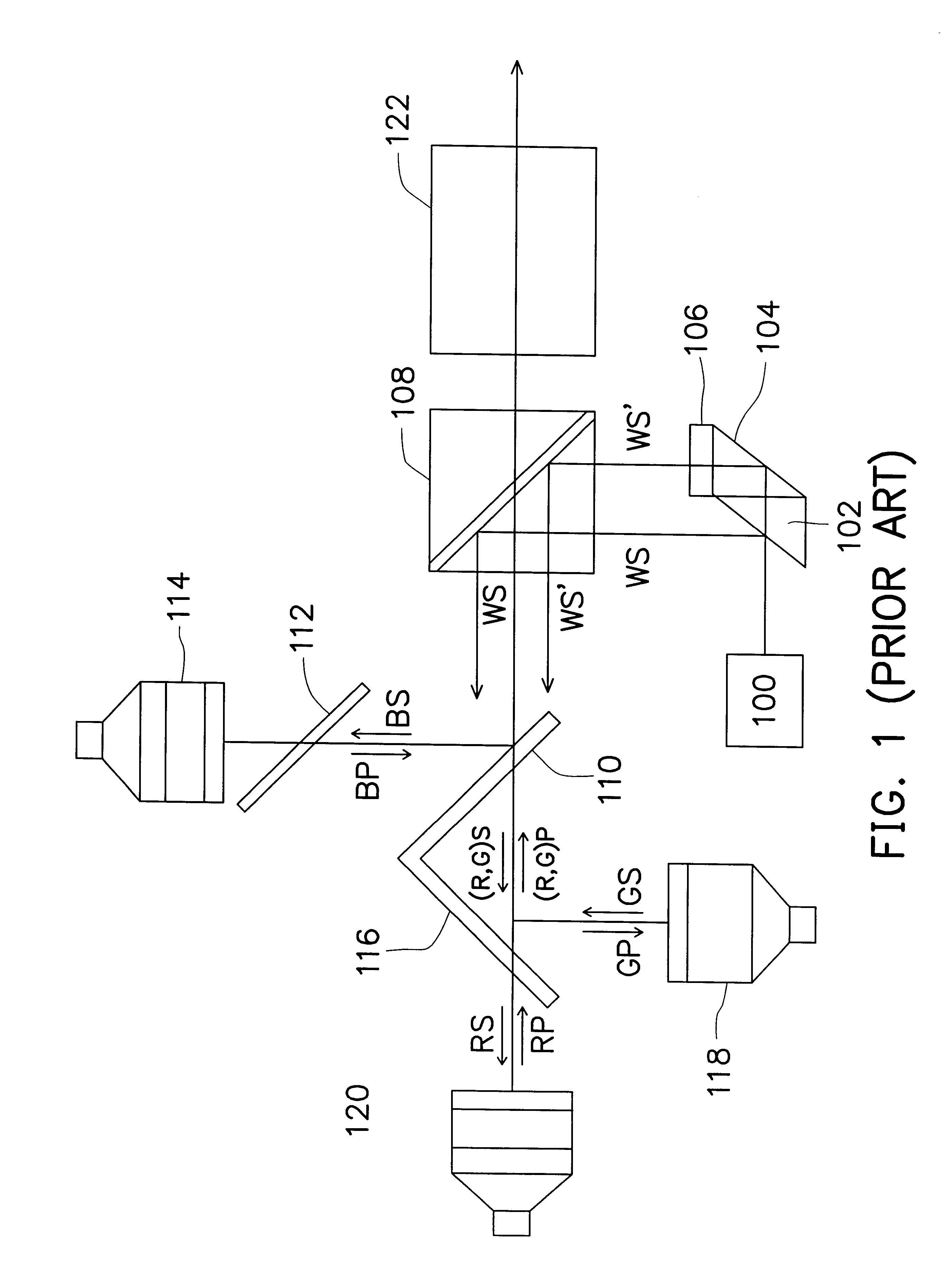
This display system cannot be efficiently applied in a large displaying area and is not portable.
Moreover, a poor focusing quality severely occurs due to a too large distance between the LCLVs and the projection lens.
This further limits its applications.
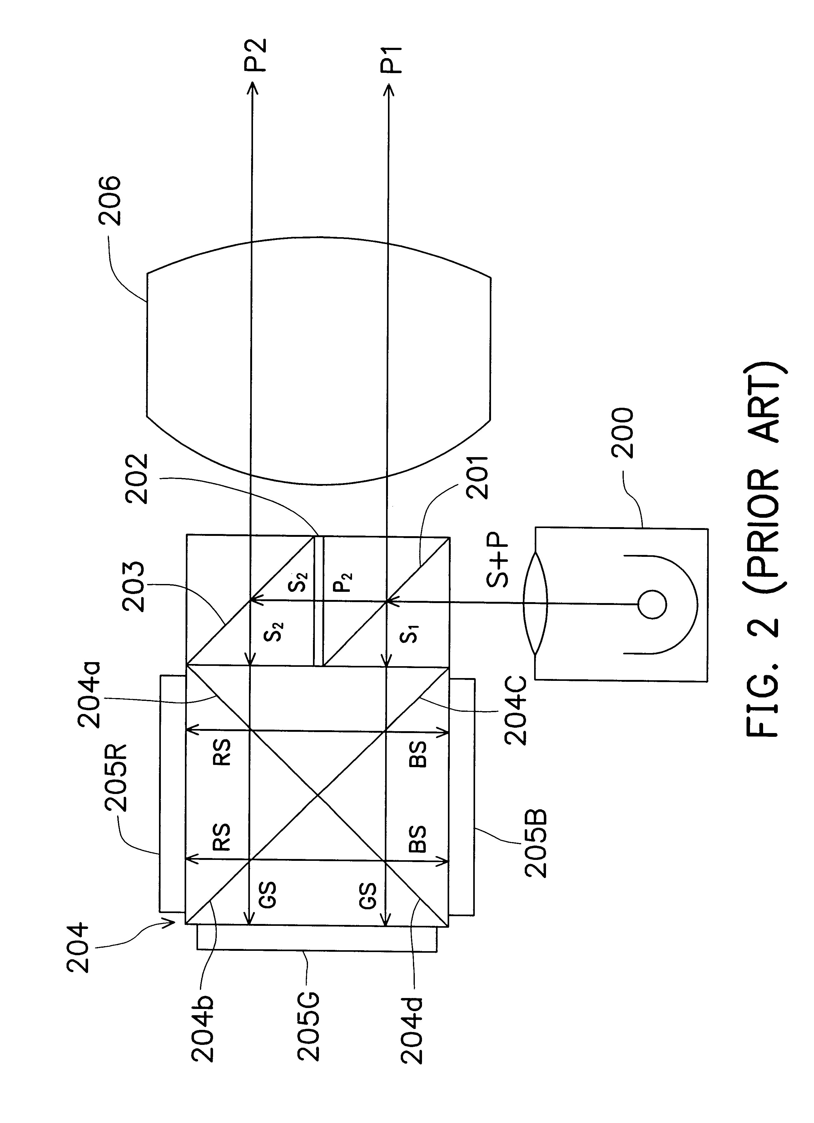
However, since the system of FIG. 2 is very complicate, production yield rate is low and fabrication cost is high.
Moreover, since several prisms are used in the system, a little misalignment may cause a large error.

Method used


Image

  • Liquid crystal display system and light projection system
  • Liquid crystal display system and light projection system
  • Liquid crystal display system and light projection system

Examples


Embodiment Construction

The conventional projection system used in a LCD system includes issues of, for example, large dimension, poor focusing quality, complicate system, or high fabrication cost. The invention introduces a projection system used in a LCD system so as to at least solve the above issues.

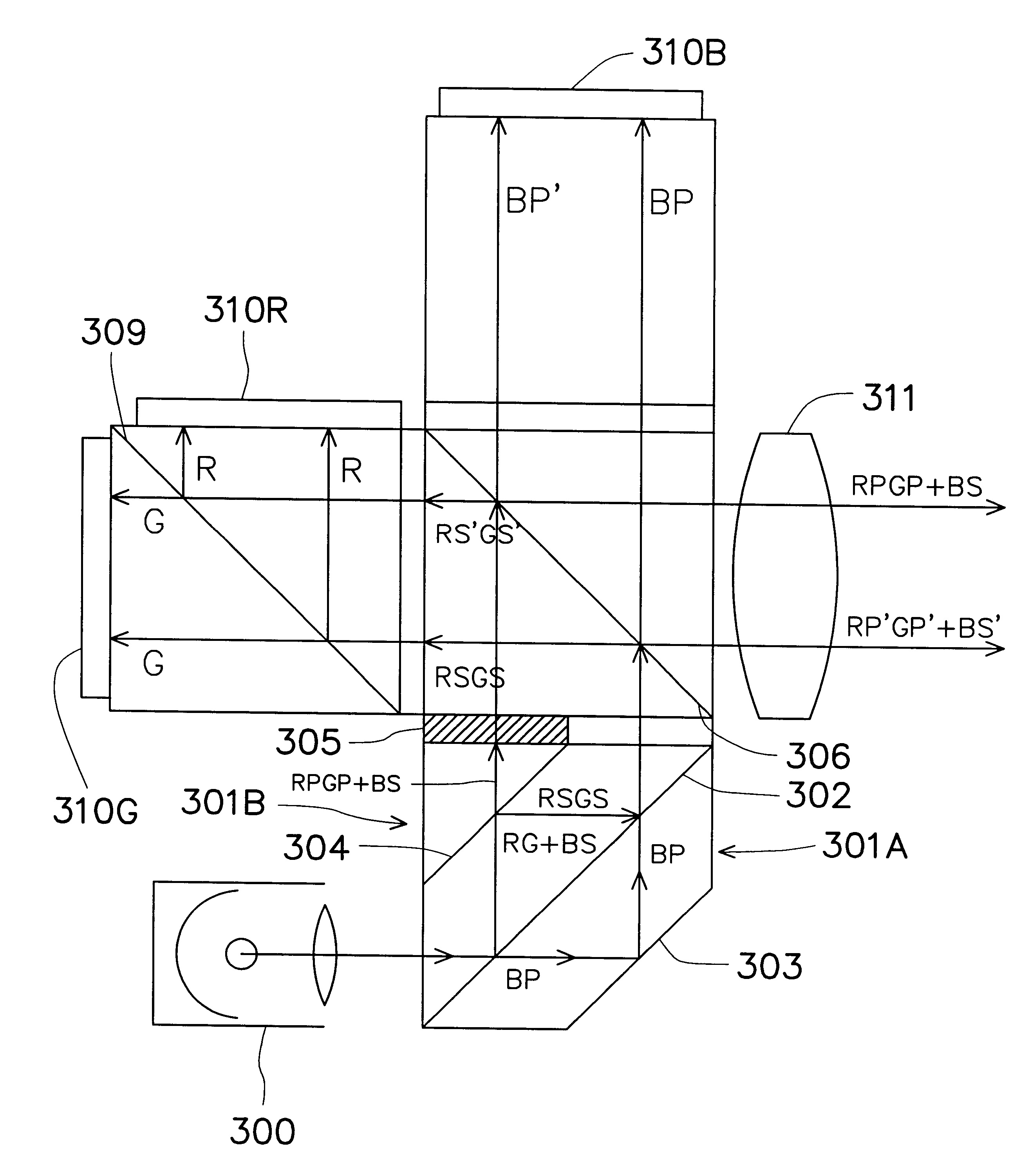
FIG. 3 is a structure diagram, schematically illustrating a polarization light projection system using reflection-type LCD panels, according to a preferred embodiment of the invention. In FIG. 3, a greatly simplified projection system is designed so that dimension is greatly reduced, a back focal length is also reduced. The system has a large tolerance of misalignment. Fabrication cost is also reduced.

The projection system of the invention includes a light source 300, a double dove prism 301A, a vertical prism 301B, a half-wave plate 305, a polarization beam splitter (PBS) 306, a color filter prism 309, and a projection lens 311. The double dove prism 301A further includes optical films 302 and 304, in whic...


PUM


Abstract

A projection system used in a liquid crystal display (LCD) system is provided. The projection system has a light source, a polarization set which further includes a double dove prism, a vertical prism and a half-wave plate, a polarization beam splitter (PBS), a dichroic prism, and a projection lens. The light source emits a white light, which enters the polarization set and is split into a P-state polarized blue light and a mixed light. The mixed light includes an S-state polarized red light and an S-state polarized green light. The PBS allows the P-state polarized blue light to transmit and enter onto a blue light LCD panel, and deflects the mixed light by 90°. The dichroic prism splits the S-state polarized red light and the S-state polarized green light of the mixed light, which respectively enter a red light LCD panel and a green light LCD panel. The projection lens collects light from the red, green, blue LCD panels and project the lights onto a screen.

Description

This application claims the priority benefit of Taiwan application serial no. 87108197, filed May 26, 1998, the full disclosure of which is incorporated herein by reference.1. Field of the InventionThis invention relates to an electronic optical system, and more particularly to a light projection system suitable for a use in a liquid crystal display system (LCD) to display image.2. Description of Related ArtRecently, a LCD device is widely used in TV, computer, monitor or other display system. Comparing with a conventional display apparatus with a picture tube, the LCD system is lighter and has a smaller dimension. It becomes a necessary part to display system, such as a notebook computer.FIG. 1 is a structure diagram, illustrating a polarization light projection system used in a reflection-type color display board as disclosed by U.S. Pat. No. 5,530,489. In FIG. 1, a reading light source 100 can emit a white light. The white light is polarized by a polarization beam splitter (PBS) ...

Claims


Application Information

Patent Timeline
IPC IPC(8): H04N9/31
CPCH04N9/3105H04N9/3197
Inventor HUANG, JUNEJEIHO, FANG-CHUAN
Owner TRANSPACIFIC IP II
Learn More