Method for designing a metal mold

a metal mold and mold design technology, applied in the direction of moulding machines, instruments, moulding apparatus, etc., can solve the problems of large contracting of high-temperature molten plastic, nonlinear deformation, and inability to achieve targeted molding shapes,

Inactive Publication Date: 2001-10-16
KAO CORP
View PDF12 Cites 23 Cited by
  • Summary
  • Abstract
  • Description
  • Claims
  • Application Information

AI Technical Summary

Problems solved by technology

As a result, it was found that if a metal mold is separated before the conventionally employed cooling time has elapsed, the high-temperature molten plastic contracts greatly and undergoes nonlinear deformation.
Accordingly, the targeted molding shape could not be obtained and cooling time could not be shortened.
In the in-molding labelling, it is formed different two kinds of materials overlapping so that it is more difficult to predict deformatio...

Method used


Image

  • Method for designing a metal mold
  • Method for designing a metal mold
  • Method for designing a metal mold

Examples


first embodiment

[First embodiment]

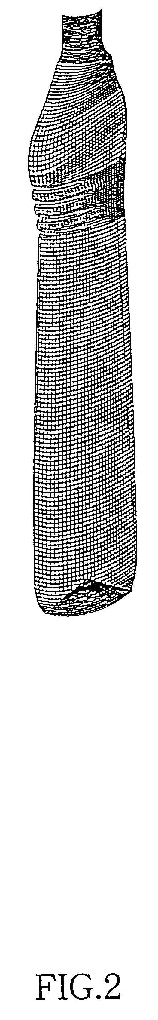
A first embodiment of this invention will be explained with reference to the bottle depicted in FIG. 2 as an example. If the taking out temperature is low, i.e. if there is very little deformation (and deformation is linear), then the metal mold shape that will give the target molding shape when the shrink deformation of the plastic that has been taken out from the metal mold is completed, can be obtained by multiplying the target molding shape by the reciprocal of the deformation ratio. However, this technique cannot be applied if the taking out temperature is high, i.e. if thermal shrink is large and nonlinear.

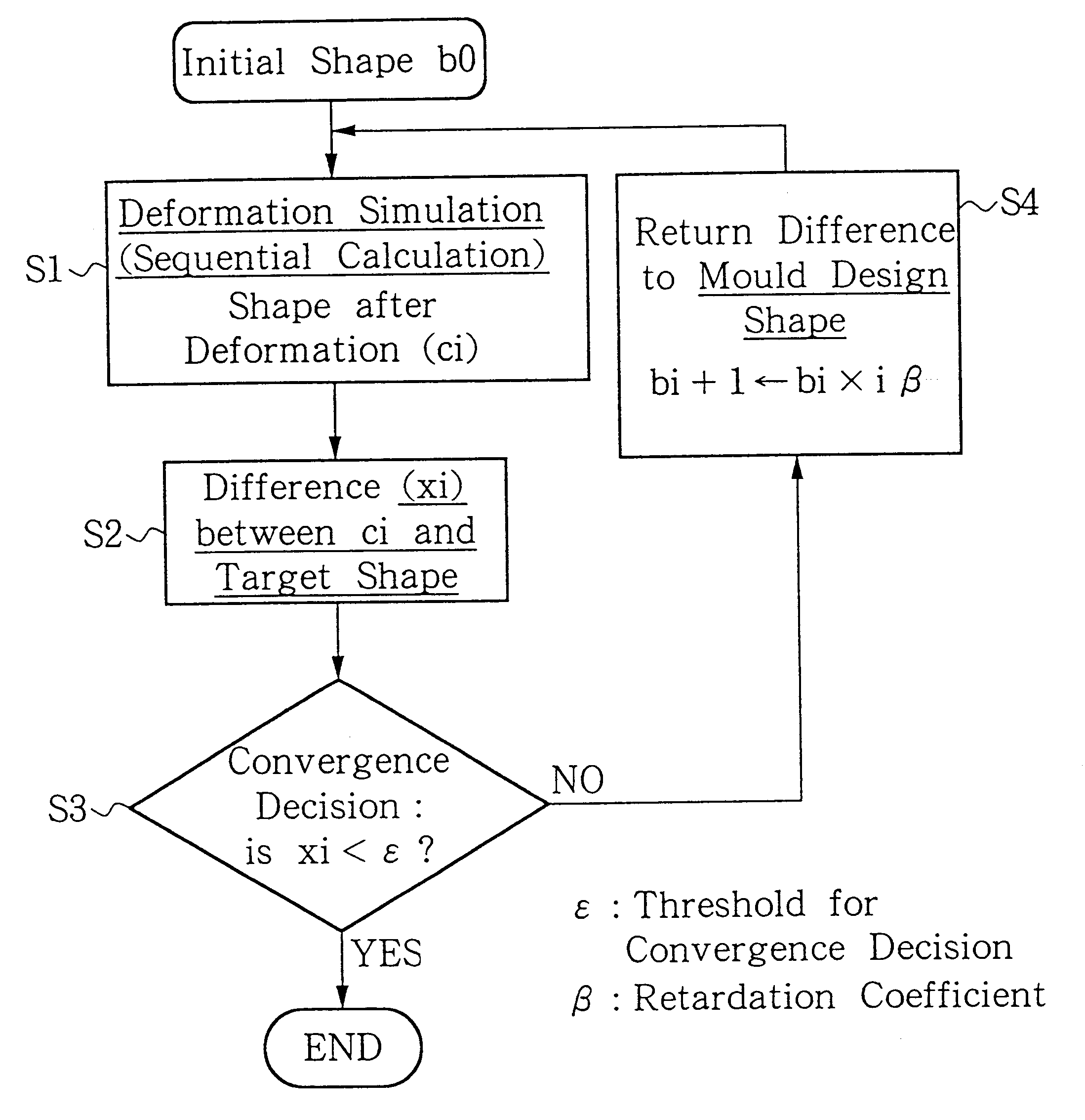
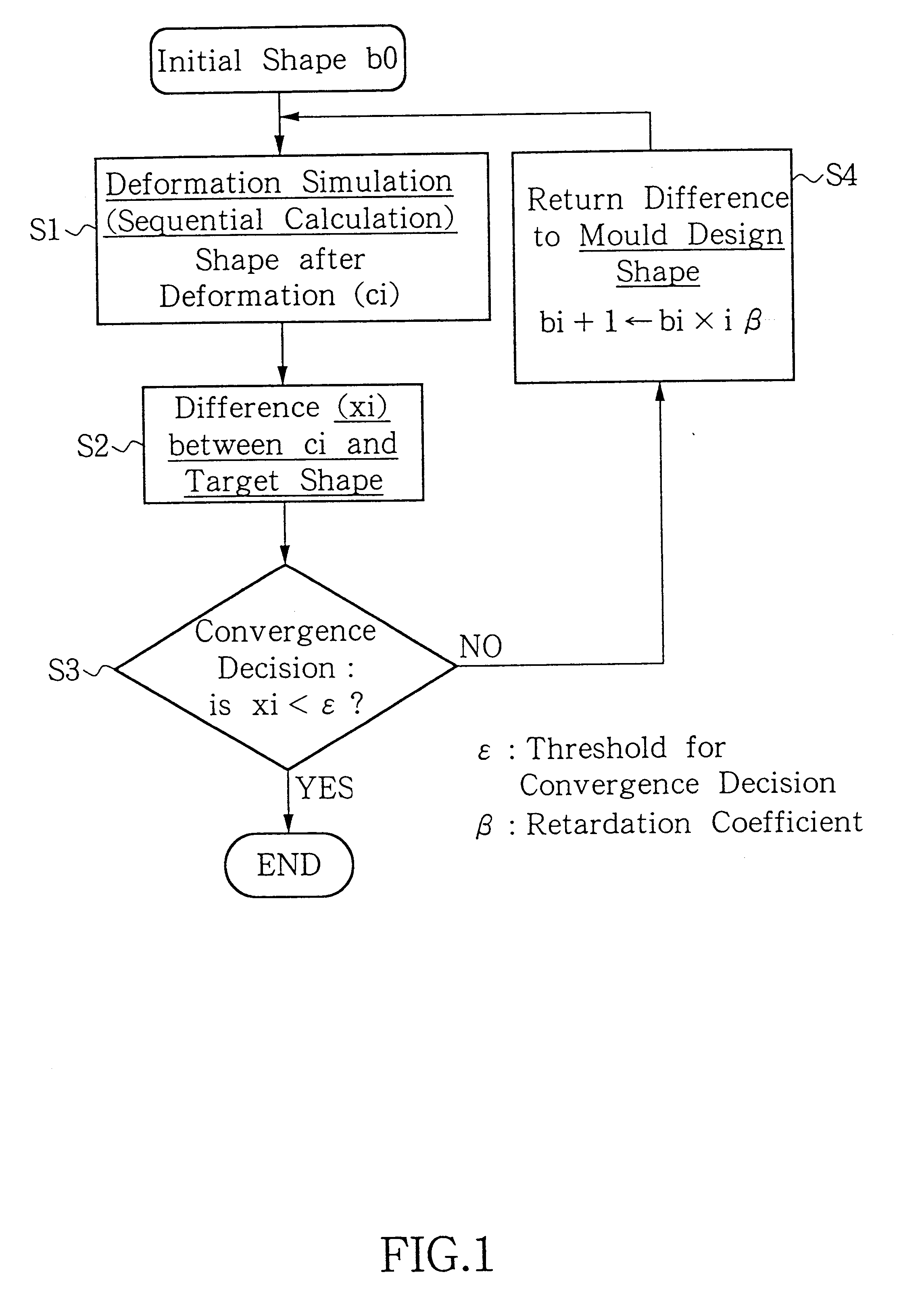
The inventors therefore repeatedly simulated the thermal deformation that occurs in the initial shape of a molding (this shape being determined by the design shape of the metal mold), and caused any difference between this simulation result and the target molding shape to be reflected in the metal mold design shape, and repeated this process until there was...

second embodiment

[Second embodiment]

A second embodiment of this invention will be explained with reference to FIG. 4, which is a flowchart of a metal mold design method according to this second embodiment. In this second embodiment, metal mold design also takes into account the deformation due to hydrostatic pressure resulting from the molded bottle having been filled with a liquid as its contents. The plastic is took out from the metal mold (S11) and undergoes thermal shrink type deformation (S12), whereby a molding is obtained (S13). As a result of this molding being filled with a liquid which constitutes its contents, it undergoes deformation due to hydrostatic pressure (S14), thereby assuming the shape of the end product (S15). In this second embodiment of the invention, this process is taken into consideration as well.

The flow of the design process proceeds in the reverse direction. That is to say, product design (S17) is carried out on the basis of a design concept (S16), and the molding is au...

third embodiment

[Third embodiment]

A third embodiment of this invention will be explained with reference to FIG. 5, which is a block diagram of a metal mold design apparatus according to this third embodiment. The metal mold design method disclosed in the first or second embodiment of this invention is performed by means of the metal mold design apparatus disclosed in this third embodiment. The initial shape of the metal mold (b0) is input in the form of three-dimensional information by means of keyboard 6. Deformation simulation arithmetic unit 1 calculates a simulation of the deformation that will occur after a molding equal in shape to this initial shape has been taken out from the metal mold. Difference arithmetic unit 2 calculates the difference between the calculated deformation and the target molding shape. Difference decision unit 3 compares this difference with a threshold. If this difference exceeds the threshold, initial shape change unit 4 applies a change to the initial shape on the bas...


PUM

PropertyMeasurementUnit
Fractionaaaaaaaaaa
Fractionaaaaaaaaaa
Fractionaaaaaaaaaa

Abstract

When a molten plastic is molded using a metal mold, sufficient cooling time has to elapse before the metal mold is opened, but this cooling time restricts the production per unit time. If a metal mold is opened without sufficient cooling, the plastic undergoes significant deformation by thermal shrink. If this deformation can be estimated and the metal mold designed so as to make allowance for the anticipated deformation, it will be possible to produce a molding with a shape that is equal to the design dimensions, despite shortening the cooling time. The finite element method is used to obtain the deformation. Mold design can also be performed taking account of the deformation due to the hydrostatic pressure that is produced when the molding is filled with its liquid contents. In addition, as for a portion of an in-mold labelled container which include lamination construction, the deformation due to thermal shrink is not estimated as a container which an in-mold label is not being applied. On this case, we have a method which is simulating deformation after adding parameters relating to the material of this label, said parameters including at least its thermal conductivity and coefficient of linear expansion. The thermal conductivity deformation simulation is by the finite element method. Production per unit time can be increased and metal mold design can be carried out independently of experience.

Description

This invention is utilized in the design of metal molds for plastic products. It relates to a technique for shortening the time required for the plastic molding process by taking out the plastic molding from the metal mold at high temperature after having made allowance in the metal mold design for the deformation that occurs when the molding cools after taking out.BACKGROUND TECHNOLOGYA widely-used method for molding plastic is to extrude high-temperature molten plastic in a tubular shape, enclose this in a metal mold and make the tube expand by blowing air into it. A prior art example of this will be explained with reference to FIG. 10, which shows the process of manufacturing a container by blow molding. As shown in FIG. 10(a), molten plastic in tubular shape (the parison) is extruded into the middle of a split metal mold, and as shown in FIG. 10(b), the metal mold is then closed. As shown in FIG. 10(c), when air is blown into the molten plastic, the plastic adheres closely to th...

Claims


Application Information

Patent Timeline
IPC IPC(8): B29C37/00B29C33/38B29C49/00B29C35/00B29C35/16B29C49/04B29C49/24
CPCB29C33/3835B29C37/005B29C49/00B29C35/16B29C49/04B29C49/24B29C2037/90B29C49/42402B29C49/42398
Inventor NISHIMINE, NAOHIDETORII, HISANORIOJI, NOBUNORISUGAI, KEIICHIROTAMIYA, YUKO
Owner KAO CORP
Why Eureka
Try Eureka