
Boxed-in slot antenna with space-saving configuration

a boxedin slot and configuration technology, applied in the field of antennas, can solve the problems of unsuitability, unsuitability, and unsuitability of the second position, and achieve the effect of reducing the space occupation, and reducing the size of the space occupation

Inactive Publication Date: 2001-10-23
LENOVO PC INT
View PDF5 Cites 79 Cited by
  • Summary
  • Abstract
  • Description
  • Claims
  • Application Information

AI Technical Summary

Benefits of technology

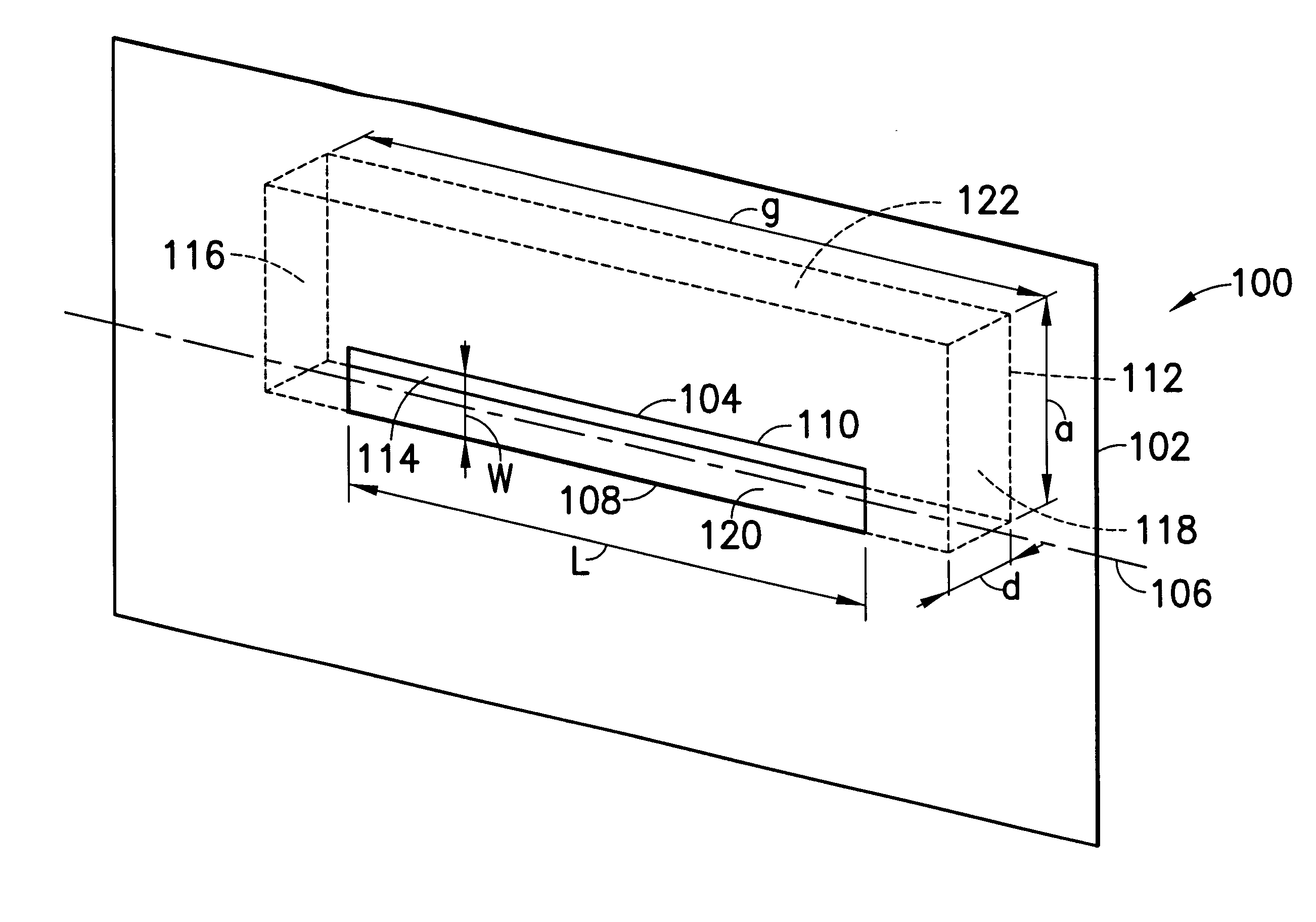
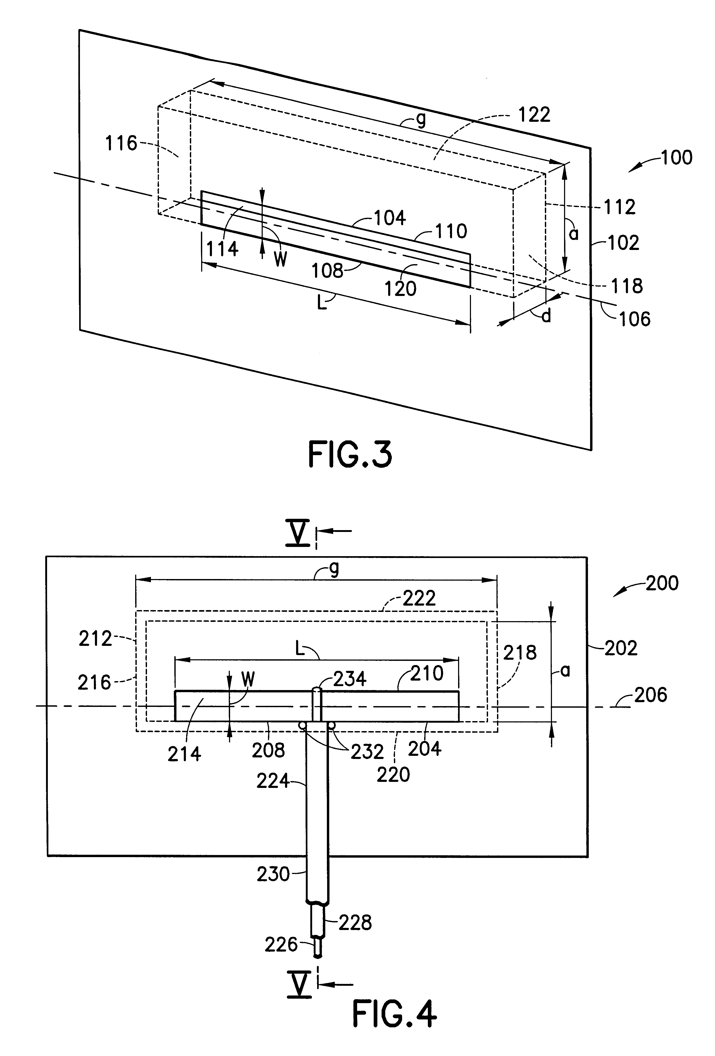
Accordingly, it will be appreciated that the inventive antenna is an improvement over the prior-art boxed-in slot antenna, inasmuch as the arrangement just described provides a folded, space-saving configuration for the conductive box structure which permits its incorporation into space-limited locations such as a laptop computer. In particular, the distance d can be much less than the distance h in the prior-art type of boxed-in slot antenna.

Problems solved by technology

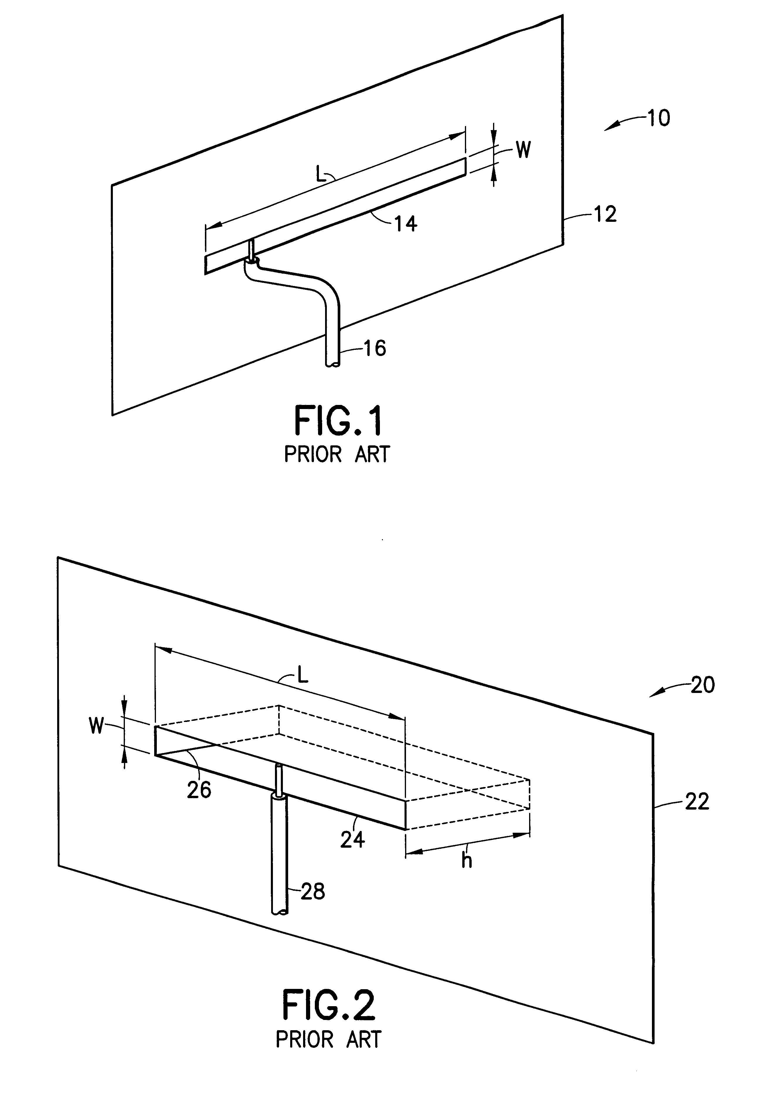
However, the folding of the monopole has undesirable effects on the electrical match, frequency bandwidth and electromagnetic fields, requiring the introduction of a shunt inductance between the monopole and the ground plane.
The original slot antenna 10 is not appropriate for use in a handheld electronic device or a laptop computer because of the radiation in both directions, while the prior art boxed-in slot antenna of FIG. 2 is also unsuitable, as the distance h must be so large that the antenna occupies an unacceptably large space.
It will be appreciated that the prior art folded monopole approach of the aforementioned WIPO publication results in unadvantageous changes to the electrical match, frequency bandwidth and electromagnetic fields, necessitating the introduction of a shunt inductance.
Further, the slot antennas discussed immediately above are unsuitable due to either bi-directional radiation or excessive size.

Method used


Image

  • Boxed-in slot antenna with space-saving configuration
  • Boxed-in slot antenna with space-saving configuration
  • Boxed-in slot antenna with space-saving configuration

Examples


Embodiment Construction

Performance of a boxed-in slot antenna, with the inventive folded, space-saving configuration for the conductive box structure, was predicted via simulation with Zeland's IE3D computer program. Performance of an embodiment of the invention similar to that shown in FIG. 10 was predicted (i.e., g=L, a=w+.lambda..sub.g / 4), but for a printed circuit board configuration, fed by a coaxial cable, similar to that shown in FIGS. 6 and 7 (but, as noted, with g=L). The conductive ground plane had a dimension of 70 mm perpendicular to the slot and 99 mm parallel to the slot. The slot width was w=3 mm, with g=L=50.5 mm. The first PCB substrate had a thickness of 3 mm and a relative dielectric constant of 4.6. A value of .lambda..sub.g / 4=19.75 mm was used such that a was 22.75 mm.

FIG. 19 depicts the predicted voltage standing wave ration (VSWR) of the antenna. The 2:1 VSWR bandwidth is 154 MHz, which is sufficiently wide for 2.4 GHz ISM applications. FIG. 20 shows the simulated elevation plane ...


PUM


Abstract

The boxed-in slot antenna is provided with a conductive box, functioning as a waveguide, which is configured substantially parallel to the ground plane in which the slot is formed, thereby providing significant space savings relative to prior art designs wherein the box is positioned perpendicular to the conductive ground plane. The inventive antenna can be easily constructed using printed circuit board technology, by forming the ground plane as a coating on one side of a printed circuit board substrate, forming the main conductive plane of the conductive box structure on the other side of the printed circuit board, and interconnecting the two using plated through holes (that is, vias). The folded structure of the conductive box of the present invention makes it particularly suited for space-critical applications, such as may be found in laptop computers and other portable and handheld electronic devices, which it is desired to interconnect with a wireless local area network (wireless LAN).

Description

1. Field of the InventionThe present invention relates to antennas, and more particularly relates to a boxed-in slot antenna having a folded, space-saving configuration, which can be employed in space-critical applications, such as a laptop computer.2. Brief Description of the Prior ArtThere is increased interest in enabling laptop computers and other portable electronic devices to interface with a wireless local area network (WLAN). WLANs may operate under a number of standards, for example, the so-called "Bluetooth" standard. In such systems, an antenna is required to send and receive data via radio frequency (RF) communications.In portable electronic devices, space is typically at a premium. Accordingly, it is desirable to minimize space to be occupied by an antenna in such devices. One prior art approach to providing an RF antenna which takes up minimal space is disclosed in World Intellectual Property Organization (WIPO) international publication number WO 95 / 06338 published on...

Claims


Application Information

Patent Timeline
IPC IPC(8): H01Q13/10H01Q23/00H01Q13/18H01Q1/38G06F1/16H01Q1/22
CPCH01Q23/00H01Q1/38H01Q13/18
Inventor LIU, DUIXAN
Owner LENOVO PC INT
Learn More