RF and IR bispectral window and reflector antenna arrangement including the same

a technology of reflector antenna and bispectral window, which is applied in the direction of antennas, instruments, measurement devices, etc., can solve the problems of inability to provide direct radiating aperture, inability to optimize reflectors, and undesirable side effects of infrared (ir) signals

Inactive Publication Date: 2001-10-23
MBDA DEUTSCHLAND GMBH
View PDF6 Cites 54 Cited by
  • Summary
  • Abstract
  • Description
  • Claims
  • Application Information

AI Technical Summary

Benefits of technology

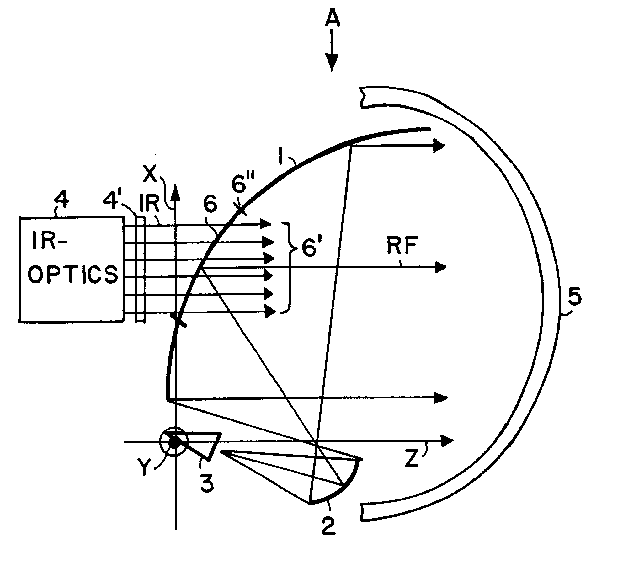
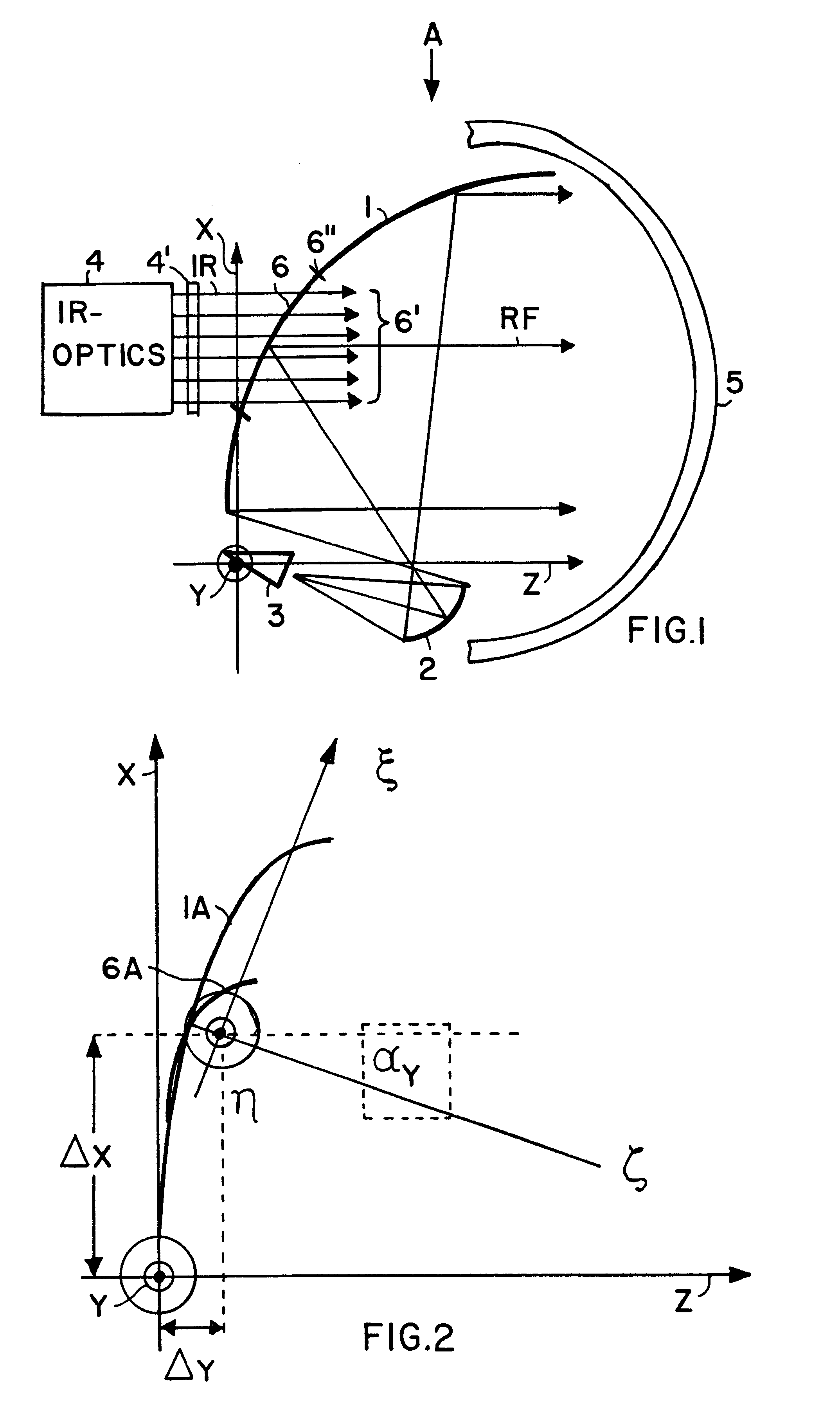
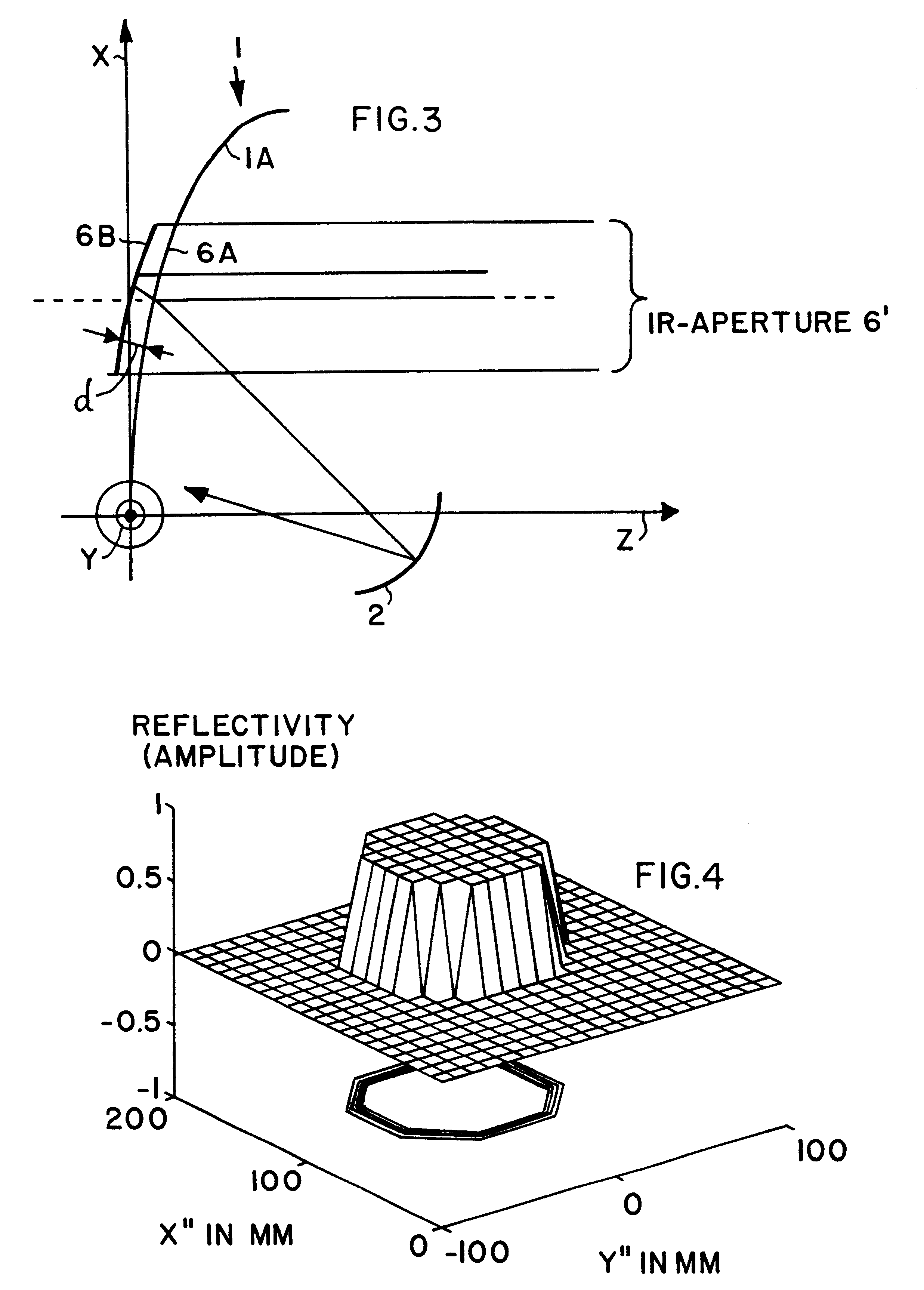
The bispectral window according to the invention, and particularly the arrangement of such a bispectral window in an opening in the central area of a main reflector of an antenna arrangement, achieves a frequency selective separation of the two signal paths of the respective IR and RF radiations. In this manner, the IR signal path does not need to follow the reflection path via main reflector and a subref lector, but instead can be transmitted and radiated directly through the bispectral window representing a direct radiation IR aperture. On the other hand, the RF radiation follows a double reflection path, being reflected from the main reflector including the bispectral window and from the subreflector. Nonetheless, the two radiation beam paths are coincident along a common axis external to the reflector antenna arrangement. By separating the beam paths in this manner, undesirable side effects on the IR radiation can be prevented while maintaining the external common beam axis. Also, the inventive integration of the two systems achieves a very compact and space-saving arrangement while still achieving the above mentioned advantages.

Problems solved by technology

With the above described known arrangement, the infrared (IR) signals suffer undesirable side effects, especially in some applications, because it is impossible to optimize the reflectors simultaneously both for the RF radiation and for the IR radiation.
Such a directly radiating aperture, however, cannot be provided in a system in which the radiation directions or radiation axes of the two radiation spectra are coincident along the common axis CA, because both the exciter as well as the subreflector would necessarily be located in the beam path and thus in the way of a direct radiation of the IR radiation.
Furthermore, it has been a continuing problem for conventional antennas to achieve a space-saving integration of a millimeter wave sensor system for RF radiation and an infrared system for IR radiation in a particularly compact arrangement, for example using an offset double reflector antenna arrangement.
Particularly, it has not been possible to achieve an acceptable antenna system having the following characteristics: a direct radiating infrared aperture without interference, the smallest possible degradation of the millimeter wave RF signal path, and a coincidence of the radiation beam axes of the two systems externally from the antenna arrangement.

Method used


Image

  • RF and IR bispectral window and reflector antenna arrangement including the same
  • RF and IR bispectral window and reflector antenna arrangement including the same
  • RF and IR bispectral window and reflector antenna arrangement including the same

Examples


Embodiment Construction

FIGS. 1 to 7 all relate to a preferred example embodiment of a reflector antenna incorporating a bispectral window according to the invention, wherein the antenna is arranged in the manner of an offset double reflector Gregorian antenna. However, other single and double reflector antenna arrangements can be embodied with a bispectral window according to the invention. For example, a Cassegrain arrangement can also utilize the present bi-spectral window, but such a Cassegrain arrangement is not as spatially compact as the present preferred offset Gregorian arrangement.

As shown schematically in FIG. 1, the present example embodiment of an offset Gregorian reflector antenna A comprises a main reflector 1, a subreflector 2, a millimeter wave RF feed horn or exciter 3, an IR optics system 4, and a radome 5, as well as a bispectral window 6 arranged according to the invention in an opening 6" provided in a central area of the main reflector 1. While FIG. 1 illustrates the situation in whi...


PUM


Abstract

A reflector antenna arrangement can transmit and receive both infrared (IR) and millimeter wave (RF) radiation. The arrangement includes a main reflector (1), a subreflector (2), an IR feed system (4), an RF feed system (3), a radome (5), and a bispectral window (6) arranged in an opening provided in a central area of the main reflector (1). The RF feed system is oriented so that the RF radiation path includes a double reflection from the subreflector and from the main reflector, while the IR feed system is arranged directly behind the bispectral window so that the IR beam path extends directly through the bispectral window without reflecting from the main reflector or the subreflector. The bispectral window has a high reflectance for the RF radiation and a high transmittance of the IR radiation. The bispectral window is made of a dielectric material and has rotationally symmetrical front and back surfaces, whereby the front surface contour is optimally matched to the front surface of the main reflector and the back surface contour achieves an optimal reflectivity of the RF radiation and an optimal transmissivity of the IR radiation. Undesired influences between the IR radiation and the RF radiation are avoided by the separation of the signal beam paths.

Description

The present invention relates to a bispectral window selectively transmitting and reflecting infrared and millimeter wave (radio frequency) radiation, as well as a reflector antenna arrangement that incorporates such a bispectral window.BACKGROUND INFORMATIONAttempts have been made in the art to provide a single antenna system that is suitable for transmitting and / or receiving radiations in more than one frequency spectrum or wavelength range. For example, the article "Multispectral (IR / MMW) Dome For seeker Application" by G. Forti, W. Menicacci--S.M.A., A. Novi, G. Simoncini, and L. Calami, OFF. GALILEO, Florence, Italy, pages 157 to 166, as published in the Sixth European Electromagnetic Structures Conference Proceedings, Friedrichshafen, Germany (1991), discloses a rotationally symmetrical Cassegrain-Antenna arrangement which is schematically shown in present FIG. 9. This conventional reflector antenna arrangement includes a primary or main reflector 101 and a secondary or subref...

Claims


Application Information

Patent Timeline
Patent Type & Authority Patents(United States)
IPC IPC(8): G01S13/00G01S13/86H01Q5/00H01Q19/10H01Q19/19H01Q5/22H01Q5/45
CPCG01S13/86H01Q5/45H01Q5/22H01Q19/192
Inventor SCHINDLER, GERHARDHAERTINGER, ERWINLEUPELT, UWE
Owner MBDA DEUTSCHLAND GMBH
Why Eureka
Try Eureka