
Offshore drilling rig and a method of operating the same

a technology of drilling rig and rotary drilling, which is applied in the direction of drilling pipes, drilling borehole/well accessories, rotary drilling, etc., to achieve the effect of reducing horizontal induced load, increasing lifting capacity, and facilitating the operation of the sam

Active Publication Date: 2016-01-28
NOBLE DRILLING AS
View PDF6 Cites 21 Cited by
  • Summary
  • Abstract
  • Description
  • Claims
  • Application Information

AI Technical Summary

Benefits of technology

The patent text describes a drilling rig that has a compact and space-saving arrangement of equipment on the drilling rig. The drill deck has a storage area for storing pipes and other operational equipment. The pipe storage area is located next to the horizontal pipe handling devices. The drilling rig also has a connecting tool that can be carried by two different load carriers, which allows for higher lifting power. The drilling rig may have three work centers arranged in the drill deck horizontally spaced apart from each other's in mutually different distances from the vertically extending track. The offshore drilling rig may also have a retractable dolly for providing vertical lifting power. The horizontal track is preferably linear and the diverter system includes a diverter over board tube that can be kept tight during drilling operations. The technical effects of the patent text include a more efficient and space-saving arrangement of equipment on the drilling rig, increased lifting capacity, and improved redundancy and efficiency.

Problems solved by technology

As such large dollies are not practical to operate fir different reasons, but also because it is expensive to implement dollies providing a substantial reach, then the offshore drilling rig may advantageously comprise at least three work centers arranged in the drill deck horizontally spaced apart from each other's in mutually different distances from the vertically extending track.

Method used


Image

  • Offshore drilling rig and a method of operating the same
  • Offshore drilling rig and a method of operating the same
  • Offshore drilling rig and a method of operating the same

Examples


Embodiment Construction

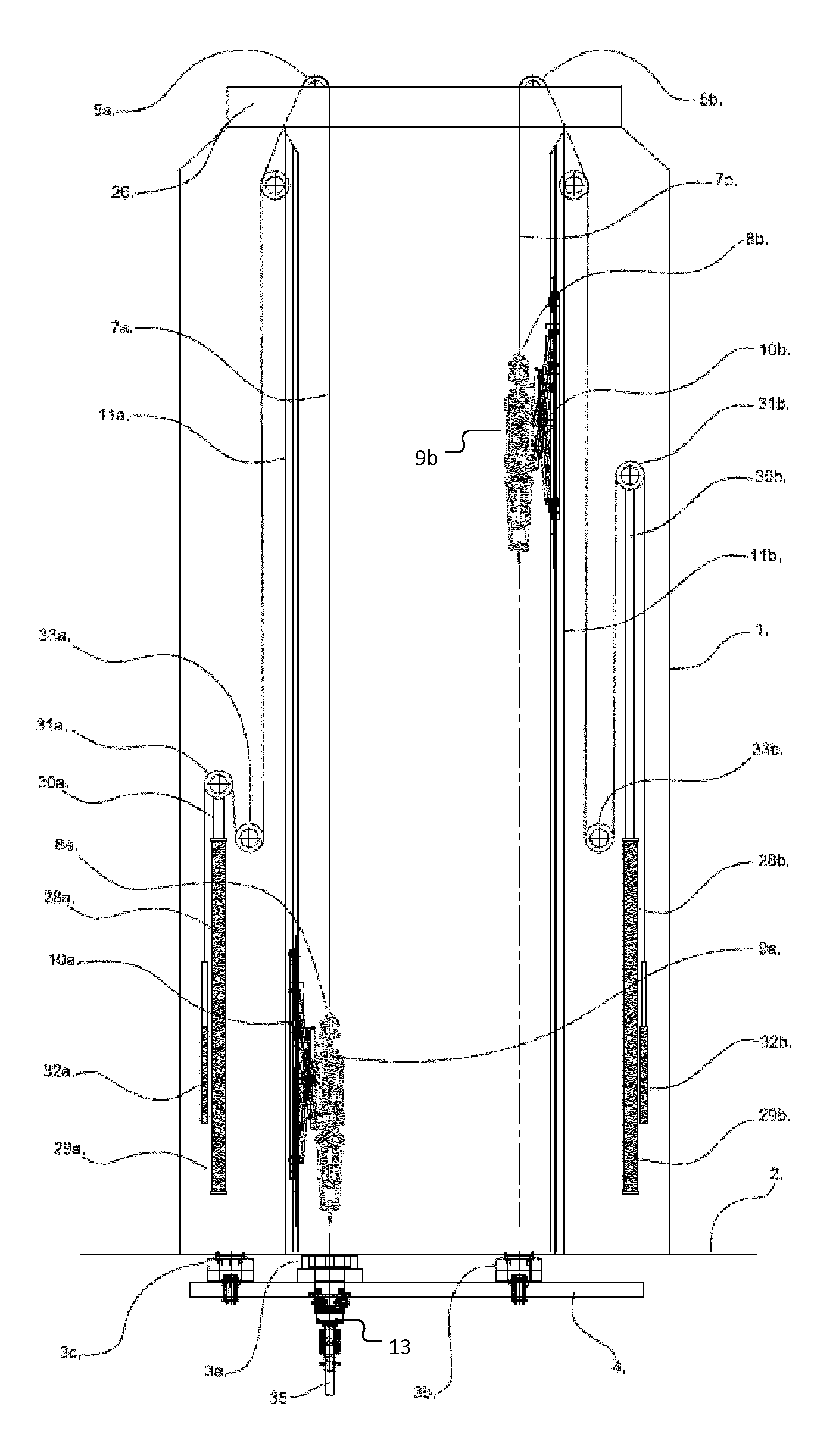
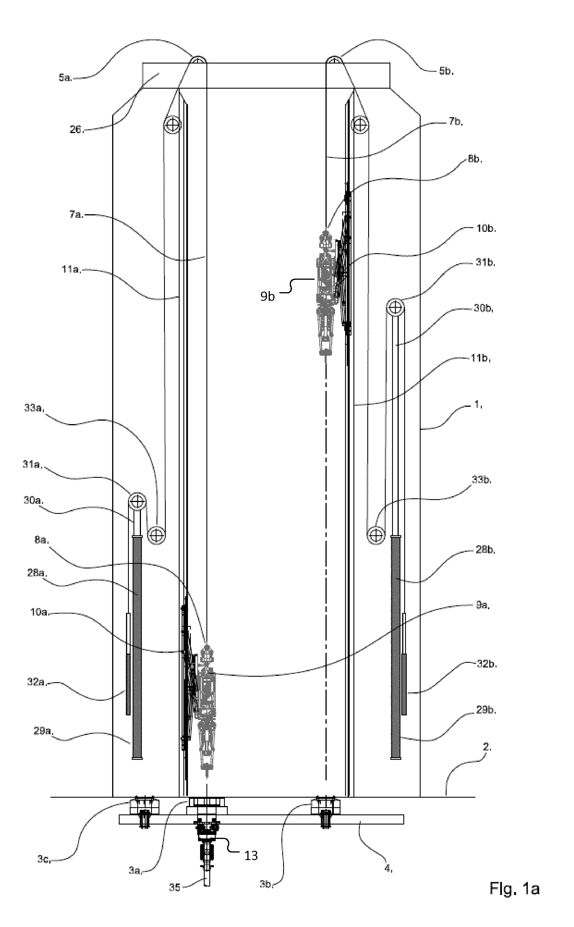
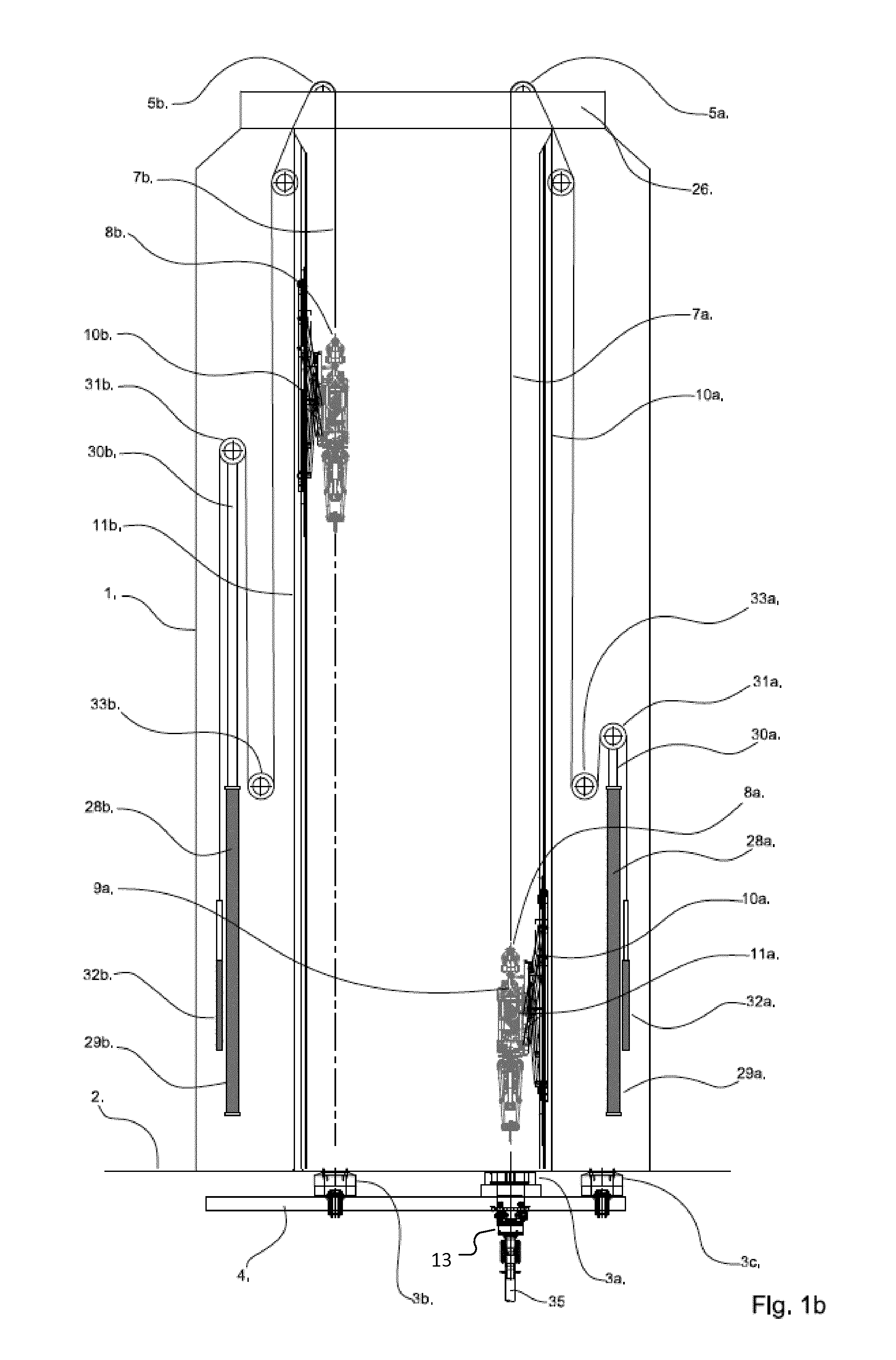
[0046]FIGS. 1a, 1b, 2a, 2b and 4 all shows a drilling support structure 1 arranged above a drill deck 2 and three work centers 3a, 3b and 3c, where one is in the form of a primary well center 3a being equipped with a diverter housing 13. The three work centers 3a, 3b and 3c are supported on individual skid-bases on tracks 4 arranged in the drill deck 2, and the drilling support structure 1 carries two cable crowns 5a and 5b on FIGS. 1a, 1b, 2a, 2b and 4 in the form of a crown sheave cluster, and on FIG. 3 in the form of a crown block, being skidably arranged on the top of the drilling support structure 1 on separate tracks.

[0047]From each of the crown sheave clusters 5a and 5b lifting cables 7a and 7b are running down and connecting to a load carrier 8a and 8b each carrying a top drive 9a and 9b at the end of the lifting cables 7a and 7b. Each of the top drives are connected via a retractable dolly 10a and 10b to a vertical track 11a and 11b arranged at the drilling support structur...


PUM


Abstract

An offshore drilling rig comprising a drill deck, at least one primary well center and a diverter system arranged below the primary well center, a drilling support structure extending upwardly from the drill deck and above the primary well center and the other work center and a first and a second hoisting system supported by the drilling support structure and being adapted for raising or lowering a first and a second load carrier, respectively, and where the offshore drilling rig comprises a positioning system adapted for selectively positioning at least the first load carrier in at least a first or a second horizontal position different from the first horizontal position, where the first load carrier in the first horizontal position is positioned above the primary well center, and in the second horizontal position is positioned above the other work center.

Description

THE PRIOR ART[0001]The present invention relates to an offshore drilling rig comprising a drill deck and a drilling support structure extending upwardly from the drill deck, and where at least one or two work centers are arranged in the drill deck, at least one of the work centers being a primary well center meaning that it is equipped for drillings operations using a diverter that can be connected to a mud return system, such as a marine riser or a mud return conductor being capable of conducting drilling mud from the sea floor to the offshore drilling rig.[0002]Offshore drilling rigs of this kind are expensive to build and operate, and the continued development of this kind of rigs is therefore focused on providing a rig that will reduce the time of production, meaning that the time for drilling and installing the necessary equipment for e.g. oil production shall be as short as possible preferably without significantly increasing the costs of building and operating the rig.[0003]F...

Claims


Application Information

Patent Timeline
Patent Type & Authority Applications(United States)
IPC IPC(8): E21B15/02E21B7/12E21B19/084
CPCE21B15/02E21B7/12E21B19/084E21B19/143E21B21/001E21B3/022E21B19/006E21B19/155
Inventor KANNEGAARD, MICHAELMCCOLL, ALLANHOLCK, JESPER
Owner NOBLE DRILLING AS
Learn More