Apparatus for sorting waste materials

Inactive Publication Date: 2001-11-06
BINDER
View PDF14 Cites 62 Cited by
  • Summary
  • Abstract
  • Description
  • Claims
  • Application Information

AI Technical Summary

Benefits of technology

If the grate-like conveyor belt has an upper strand and a lower strand, and the blow-out nozzles are arranged between the upper and lower strand of the grate-like conveyor belt, a precise triggering of the elements to be sorted out can be performed, as the blow-out nozzles can be arranged only a few millimeters below the surface on which the waste material to be sorted out is disposed. Even in the case of an increase of the conveyor belt speed it is thus still possible to achieve a high precision in the sorting.
The removal devices have the advantage that the pieces of waste which are blown against can be blown either directly onto the removal device and can then be distributed further, with the local conditions being irrelevant. Depending on the sorted materials, the various receptacles can also be located in different rooms for example or the sorted materials can be supplied directly to an apparatus for further processing without requiring any intermediate storage.
The removal devices may be conveyor belts having an upper strand and a lower strand, the upper strand of the grate-like conveyor belt extending between the upper and lower strands of the conveyor belts constituting the removal devices. This allows a compact design of the apparatus in accordance with the invention, which can be used in a manner so as make best use of the available space.
The catching devices have the advantage that the apparatus in accordance with the invention is insensitive to imprecisions in the blow-out apparatuses and the different weights of the pieces of waste. If a piece of waste is not exactly blown against or if the weights of the pieces of waste vary within a certain margin, it can happen that the pieces of waste that are blown out do not come to lie precisely on the removal apparatus. As result of the catching apparatuses in accordance with the invention, however, the pieces of waste are conveyed in every single case onto the removal apparatus, even if the flight path of the pieces of waste is too short or too long.

Problems solved by technology

Both steps are problematic, since the spatial expansion of the machine will grow unproportionally faster than the increase in output during the sorting of the waste materials and will soon cause problems for the accommodation of the unit at the site.
The increase of the rotational speed, on the other hand, will lead to imprecisions during the sorting.
This leads to the disadvantage, however, that it is not possible to use the entire width of the conveyor belt, as no other pieces of waste is allowed to lie between the pieces to be sorted and the thrusting or blowing apparatus.
This also leads to the disadvantage that at the end of the conveyor belt there will only be limited space for the arrangement of blow-out nozzles and for the receptacles for receiving the sorted waste pieces, thus making the sorting output of such belts very low.
If a piece of waste is not exactly blown against or if the weights of the pieces of waste vary within a certain margin, it can happen that the pieces of waste that are blown out do not come to lie precisely on the removal apparatus.

Method used


Image

  • Apparatus for sorting waste materials
  • Apparatus for sorting waste materials

Examples


Embodiment Construction

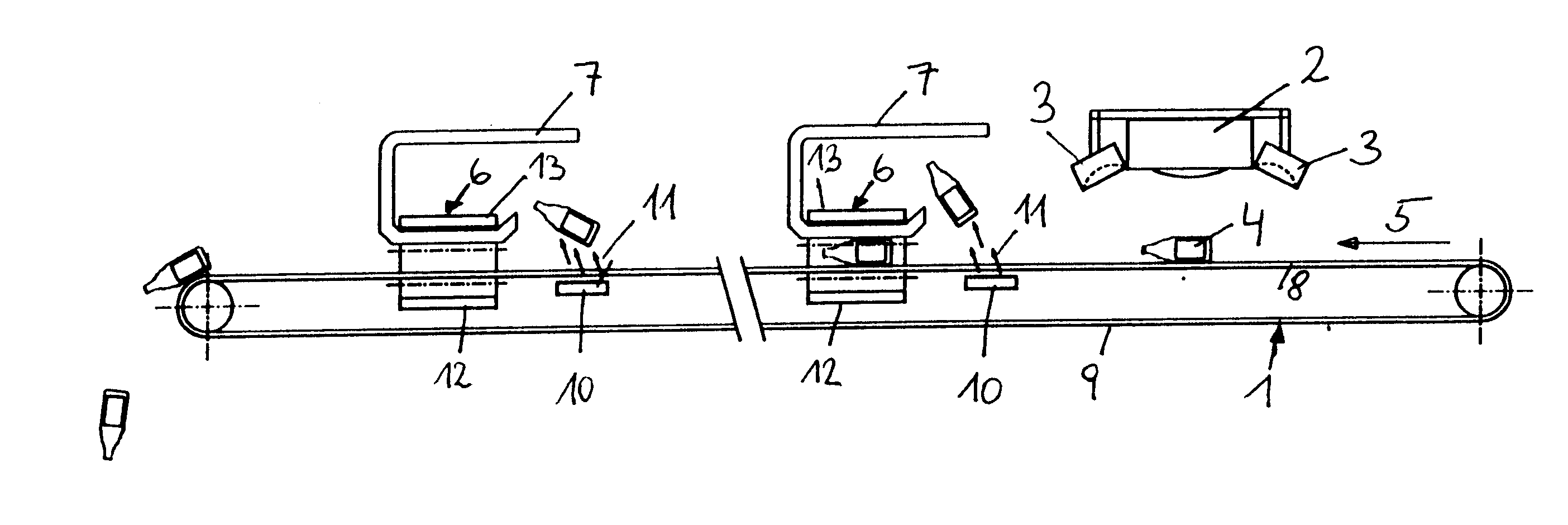
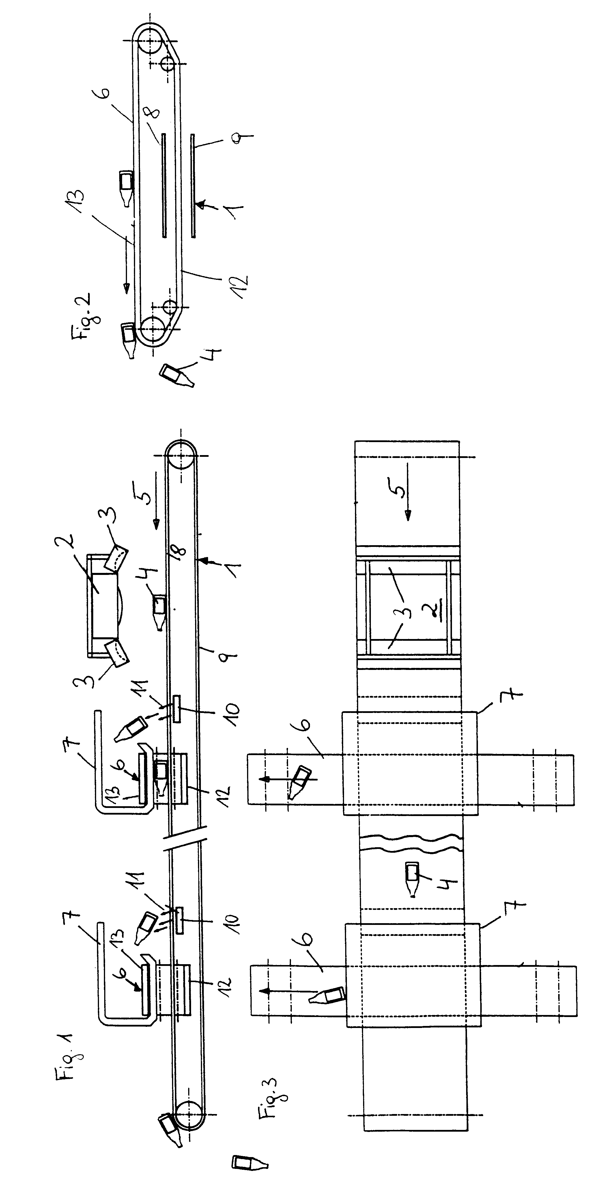
As depicted in FIG. 1, a sensor 2 is arranged above a conveyor belt 1, on the side of which are arranged lamps 3 which emit light of different wavelengths. Waste material 4 is disposed on the conveyor belt 1, in particular plastic waste such as hollow parts made of PVC, polyethylene or plastic foils, etc.. Removal devices 6 such as conveyor belts are arranged transversally to the conveying direction 5 downstream of sensor 2 as seen in the conveying direction, which removal devices are encompassed along their direction of conveyance in the zone of the conveyor belt 1 by catching devices 7 which in their cross section are substantially U-shaped.

Blow-out nozzles 10 are arranged in the conveying direction 5 upstream of the removal devices 6 below the upper strand 8 and above the lower strand 9 of the conveyor belt 1 in such a way that their blow-out direction 11 is aimed upwardly in the direction towards the removal device 6.

The sorting apparatus in accordance with the invention works a...


PUM

PropertyMeasurementUnit
Coloraaaaaaaaaa

Abstract

An apparatus for sorting waste material, in particular plastic waste and hollow parts made of plastic. The waste material to be sorted is placed in an unsorted manner on a conveyor belt and moved below a sensor. The sensor examines the waste to determine the type of material and / or the color of the material, the waste being sorted depending on the type of material or its color. The conveyor is provided with a grate-like structure, and blow-out nozzles are arranged below the conveyor belt.

Description

1. Field of the InventionThe present invention relates to an apparatus for sorting plastic waste and hollow plastic parts.2. Description of the Prior ArtKnown separating and sorting apparatuses will soon meet their limits concerning the quantity to be sorted per unit of time. From AT 402.165 so-called turntables are known, for example, in which the waste material is supplied individually to the turntable and positions itself at the edge of the same in order to be blown out at a respective location. An increase in the sorting output can only be achieved in this kind of sorting apparatus in such a way that either the rotational speed or the radius of the turntable is increased. Both steps are problematic, since the spatial expansion of the machine will grow unproportionally faster than the increase in output during the sorting of the waste materials and will soon cause problems for the accommodation of the unit at the site. The increase of the rotational speed, on the other hand, will...

Claims


Application Information

Patent Timeline
IPC IPC(8): B07C5/36B29B17/00
CPCB07C5/362B07C5/367
Inventor ANIBAS, FRANZ
Owner BINDER
Why Eureka
Try Eureka