Color picture tube

a technology of color picture and tube, applied in the direction of cathode ray tube/electron beam tube, electric discharge tube, electrical apparatus, etc., can solve the problems of resistor current leakage, change in the focusing characteristic of the main lens, etc., to prevent the change of convergence characteristic, stable and satisfactory convergence characteristic

Inactive Publication Date: 2001-11-06
KK TOSHIBA
View PDF17 Cites 5 Cited by
  • Summary
  • Abstract
  • Description
  • Claims
  • Application Information

AI Technical Summary

Benefits of technology

The present invention has been made to solve the above problems, and its object is to provide a color picture tube which prevents a change in convergence characteristic due to a current leaked from the resistor arranged in the neck during an operation of the color picture tube, so that a stable and satisfactory convergence characteristic can be obtained in the overall screen.

Problems solved by technology

However, while the color picture tube is operating, the current tends to leak from the resistor 100 arranged within the neck.
Since no measures to cope with the current leak are taken in the conventional electron gun, if the current leaks, the voltages applied to the intermediate electrodes 70 and 80 are unstable, resulting in change in the focusing characteristic of the main lens.

Method used


Image

  • Color picture tube
  • Color picture tube
  • Color picture tube

Examples


Embodiment Construction

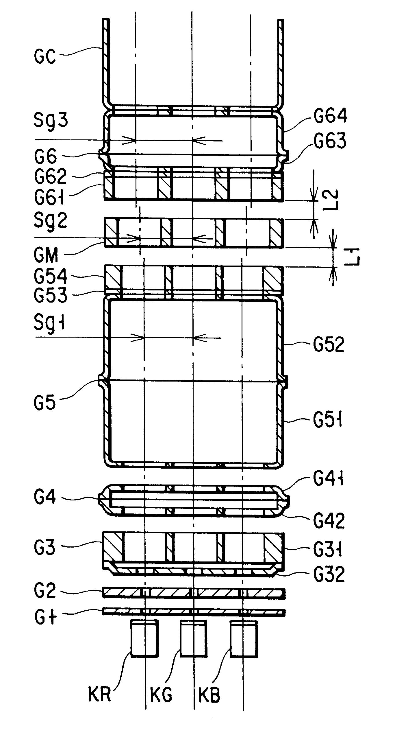
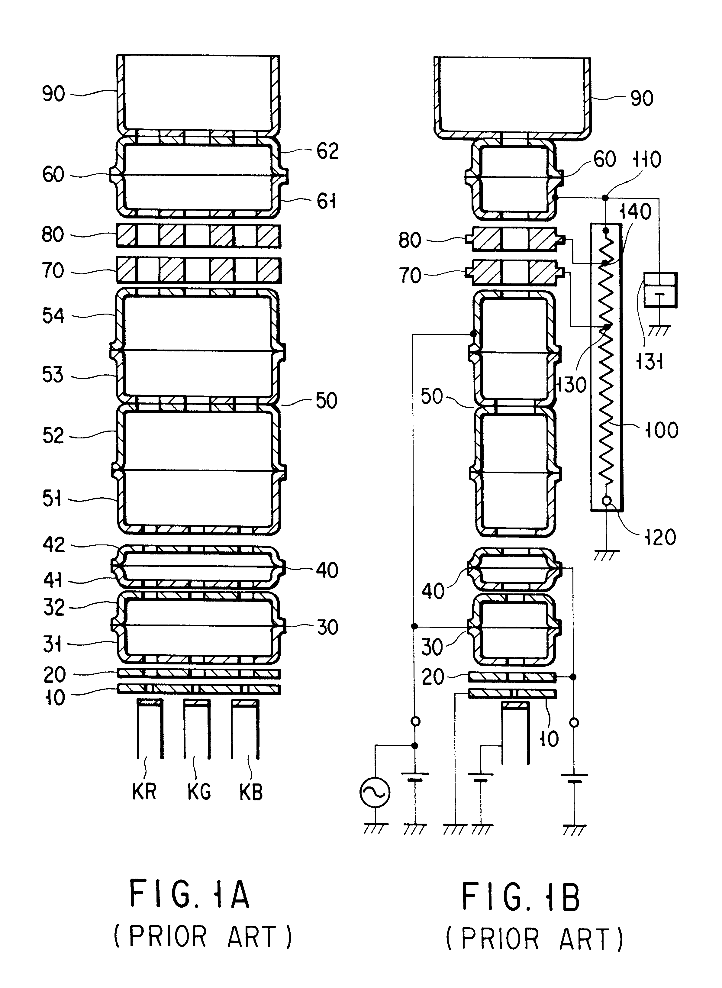
An embodiment of a color picture tube of the present invention, particularly, an electron gun applied to the color picture tube will be described with reference to the accompanying drawings.

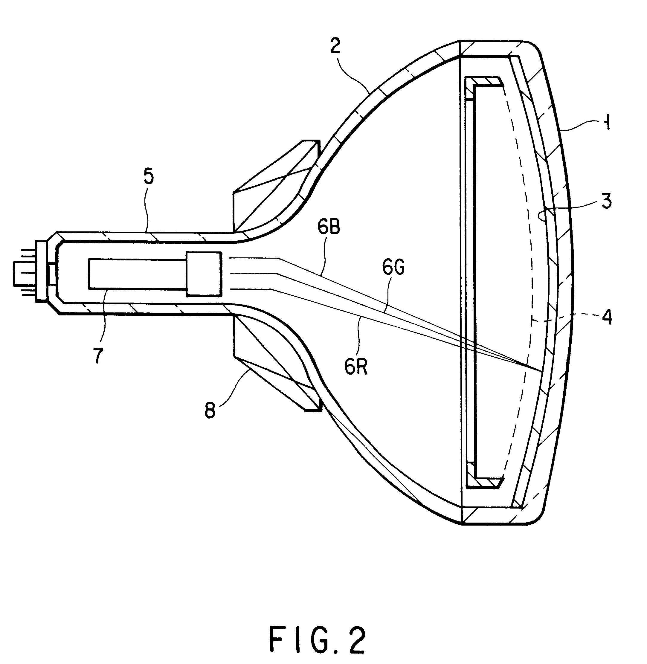
FIG. 2 is a schematic view showing an example of the color picture tube according to the present invention. The color picture tube, as shown in FIG. 2, comprises an envelope formed of a panel 1 and a funnel 2 integrally joined to the panel 1. A phosphor screen 3 (target) made of a stripe or dotted three-color phosphor layer for emitting blue, green and red light is formed on the inner surface of the panel. A shadow mask 4, having a number of apertures i.e., electron beam passage holes, is mounted on a position opposite to the phosphor screen 3.

An electron gun 7 for emitting three electron beams 6B, 6G and 6R is arranged in the neck 5 of the funnel 2. A deflection yoke 8 for generating horizontal and vertical deflection fields is mounted on the outside of the funnel 2.

In the color picture tube hav...


PUM


Abstract

A color picture tube which prevents a change in convergence due to current leaked from a resistor during operation of the color picture, thus, providing a stable and satisfactory convergence characteristic in the overall region of the screen. The color picture tube comprises a main electron lens portion, a deflection yoke, and an inline electron gun that includes an electron beam generating portion for generating three electron beams in line consisting of a center beam and a pair of side beams. Distances between the center axis of the center beam passage hole and that of each of the side beam passage holes in a first electrode (G5), a second electrode (GM) and a third electrode (G6) are represented by Sg(1), Sg(2) and Sg(3). The first and second electrodes are separated by a gap L(1); and the second and third electrodes are separated by a gap L(2). The distance Sg(2) is set to satisfy the relationship:

Description

TECHNICAL FIELDThe present invention relates generally to a color picture tube, and more particularly to a color picture tube in which an electron gun having a large-diameter main lens is mounted.BACKGROUND ARTIn general, a color picture tube is constructed to display a color image by scanning a phosphor screen in horizontal and vertical directions by a plurality of electron beams emitted from an electron gun.An example of the electron gun applied to the color picture tube is an inline electron gun, which emits three electron beams in line: a center beam and a pair of side beams on both sides of the center beam, all traveling on the same horizontal plane. A main lens portion of the electron gun is constituted by grids. The center axes of side beam passage holes, through which side beams pass in a grid on the higher voltage side of all the grids, are decentered to outer sides than those of a grid on the lower voltage side. In other words, the center axes of side beam passage holes in...

Claims


Application Information

Patent Timeline
Patent Type & Authority Patents(United States)
IPC IPC(8): H01J29/50H01J29/48
CPCH01J29/503H01J2229/4841
Inventor KIMIYA, JUNICHIHOSHINO, FUMITAKASUGAWARA, SHIGERU
Owner KK TOSHIBA
Why Eureka
Try Eureka