Mold assembly for forming ophthalmic lens, method of producing the same, and method of producing ophthalmic lens using the mold assembly

a mold assembly and lens technology, applied in the field of mold assembly for forming ophthalmic lenses, can solve the problems of high-pressure molding, inability to repeatedly use the mold in subsequent molding operations, undesirably and inevitably requires expensive equipmen

Inactive Publication Date: 2001-11-13
MENICON CO LTD
View PDF11 Cites 53 Cited by
  • Summary
  • Abstract
  • Description
  • Claims
  • Application Information

AI Technical Summary

Problems solved by technology

Moreover, the molds are easily deformed upon removal or releasing of the molded product therefrom, making it impossible to repeatedly use the molds in subsequent molding operations.
Such high-pressure molding, however, undesirably and inevitably requires expensive equipment.
If the thickness of the webs is relatively small, the male and female molds formed in the thin webs undesirably tend to be deformed during the molding operation for forming the contact lens.
Such high-pressure molding, however, undesirably and inevitably requires expensive equipment.
In this case, the soft contact lens molded in the deformed molds does not have the intended optical characteristics.
If the thickness of the thermoplastic film 10 is excessively small, the thermoplastic film 10 tends to be easily ruptured or torn, deteriorating the molding efficiency.
Further, the excessively thin thermoplastic film does not securely adhere to the body portion 8 due to the air entrapped between the thermoplastic film 10 and the convex surface 9 of the body portion 8.
On the other hand, if the thickness of the thermoplastic film 10 is too large, the molding efficiency is undesirably deteriorated, resulting in reduced productivity of the ophthalmic lens.
This would be difficult if the thermoplastic film 10 were not supported by the body portion 8.

Method used


Image

  • Mold assembly for forming ophthalmic lens, method of producing the same, and method of producing ophthalmic lens using the mold assembly
  • Mold assembly for forming ophthalmic lens, method of producing the same, and method of producing ophthalmic lens using the mold assembly
  • Mold assembly for forming ophthalmic lens, method of producing the same, and method of producing ophthalmic lens using the mold assembly

Examples


Embodiment Construction

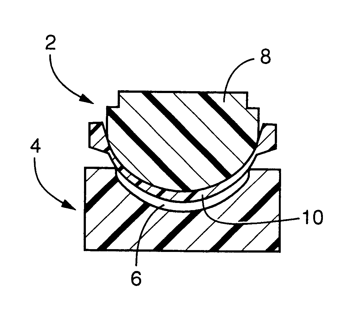
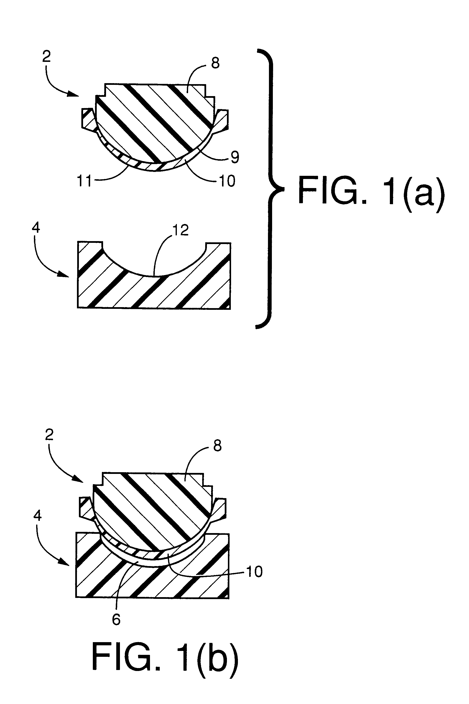
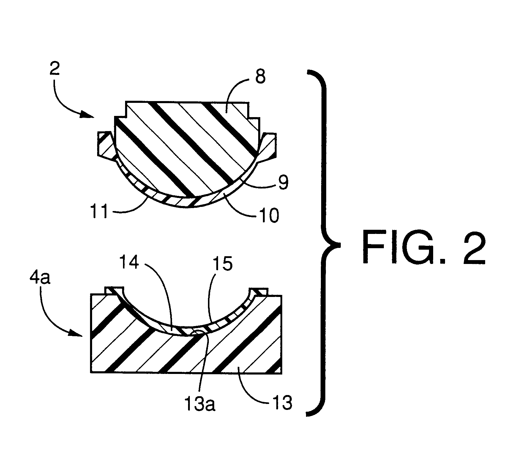
The coated male mold 2 shown in FIG. 1 was prepared in the following manner. Initially, there was prepared the body portion 8 as the first die, which is formed of polymethyl methacrylate and has a convex part-spherical surface 9 which will be coated with the thermoplastic film 10 as described below and which has a radius of 7.0 mm. Further, the second die 20 shown in FIG. 3 was prepared by using a brass material. The second die 20 has a concave part-spherical surface 20a functioning as a press forming surface for giving a convex molding surface 11 of the thermoplastic film 10, and has a diameter of 7.25 mm.

The thermoplastic film 10 was prepared by using a polyethylene (PE) film 10a having a diameter of 20 mm and a thickness of 0.5 mm. The PE film 10a was heated by an electric heater for about ten seconds at its central 14 mm-diameter circular portion, whereby the film 10a was sufficiently softened.

Next, the first die in the form of the body portion 8 prepared as described above was ...


PUM

PropertyMeasurementUnit
thicknessaaaaaaaaaa
temperatureaaaaaaaaaa

Abstract

A mold assembly for forming an ophthalmic lens, the mold assembly comprising a first mold and a second mold which cooperate with each other to define therebetween a mold cavity having a profile following that of the ophthalmic lens, wherein the improvement comprises: at least one of the first and second molds being a coated mold consisting of a body portion including a backing surface having rigidity and mechanical strength enough to withstand a molding operation for forming the ophthalmic lens in the mold cavity, and a thermoplastic film retained on the body portion such that the thermoplastic film covers the backing surface of the body portion, the thermoplastic film having a molding surface which partially defines the mold cavity and which gives a corresponding one of opposite surfaces of the ophthalmic lens.

Description

1. Field of the InventionThe present invention generally relates to a mold assembly for forming an ophthalmic lens, a method of producing the mold assembly, and a method of producing the ophthalmic lens by using the mold assembly. More particularly, the present invention is concerned with such a mold assembly for forming the ophthalmic lens such as a contact lens or an intraocular lens, which mold assembly does not suffer from undesirable deformation during a molding operation for forming the intended ophthalmic lens, to thereby permit easy and economical production of an ophthalmic lens having a desired configuration, and an advantageous method of producing such a mold assembly. Further, the invention is concerned with a method of producing the ophthalmic lens with the desired configuration at a relatively low cost, by using the mold assembly.2. Discussion of the Related ArtThere are proposed various techniques for producing an ophthalmic lens by a mold assembly consisting of a fir...

Claims


Application Information

Patent Timeline
Patent Type & Authority Patents(United States)
IPC IPC(8): B29D11/02B29D11/00G02C7/04B29C33/38B29C39/10B29C39/26B29K35/00B29L11/00C08F2/00C08F2/50
CPCB29D11/00432B29D11/00548B29D11/023B29L2011/0041Y10S425/808B29D11/00038
Inventor ISHIHARA, KENICHITOGO, MOTONOBU
Owner MENICON CO LTD
Why Eureka
Try Eureka