Low-loss surface acoustic wave filter on quartz substrate with optimized cut

a low-loss surface acoustic wave and filter technology, applied in piezoelectric/electrostrictive/magnetostrictive devices, piezoelectric/electrostriction/magnetostriction machines, electrical instruments, etc., can solve the problem of limiting the thickness that can be used in practice, the maximum thickness of the electrode, and the sensitivity to the technological uncertainties of manufactur

Inactive Publication Date: 2001-11-13
SNAPTRACK
View PDF12 Cites 23 Cited by
  • Summary
  • Abstract
  • Description
  • Claims
  • Application Information

AI Technical Summary

Problems solved by technology

It must be noted however that, when a device is being designed, the reflection coefficient is limited by the maximum thickness of the electrodes that can be made.
Furthermore, the sensitivity to the technological uncertainties of manufacture (in terms of the thickness of the metallization or the line width) is all the greater as the thickness of the metallization is great.
This limits the thickness that can be used in practice.
However the introduction and increasingly widespread use of reflective elements in the new types of filters is giving rise to an additional constraint that makes the ST-cut relatively less worthwhile when the greatest importance is placed on the reflection coefficient of a reflector, especially when it is made of aluminum.

Method used


Image

  • Low-loss surface acoustic wave filter on quartz substrate with optimized cut
  • Low-loss surface acoustic wave filter on quartz substrate with optimized cut
  • Low-loss surface acoustic wave filter on quartz substrate with optimized cut

Examples


Embodiment Construction

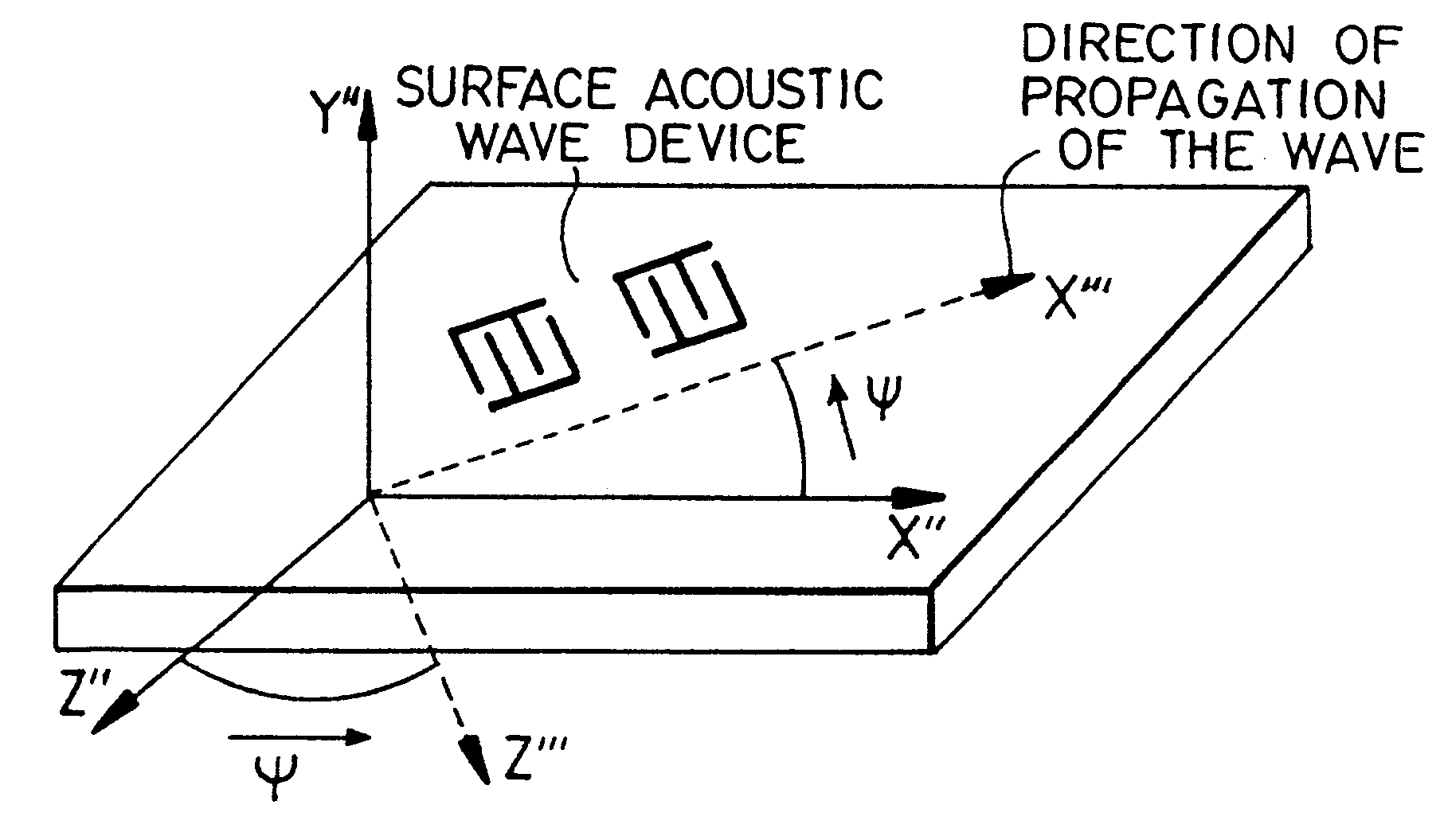
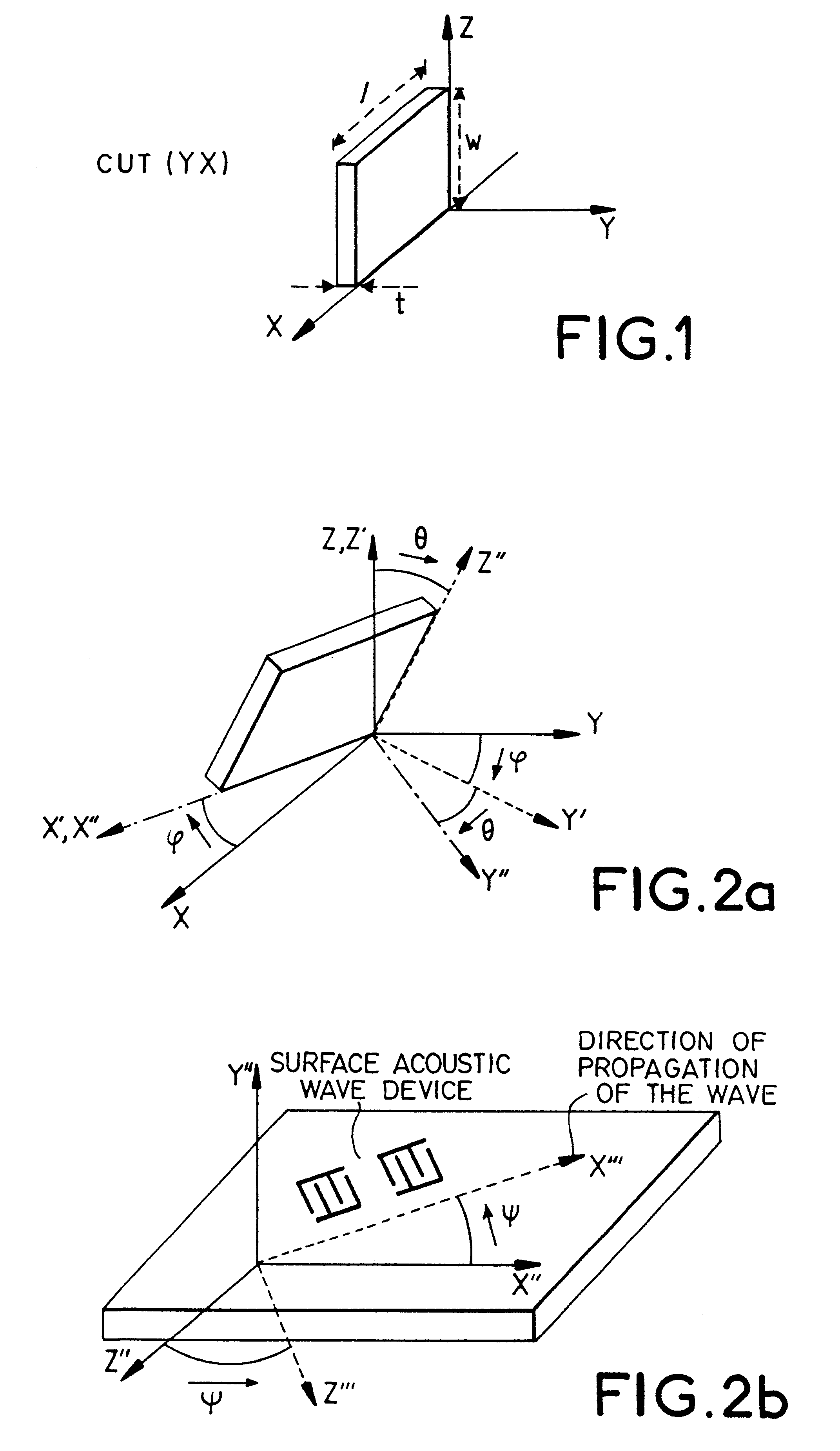
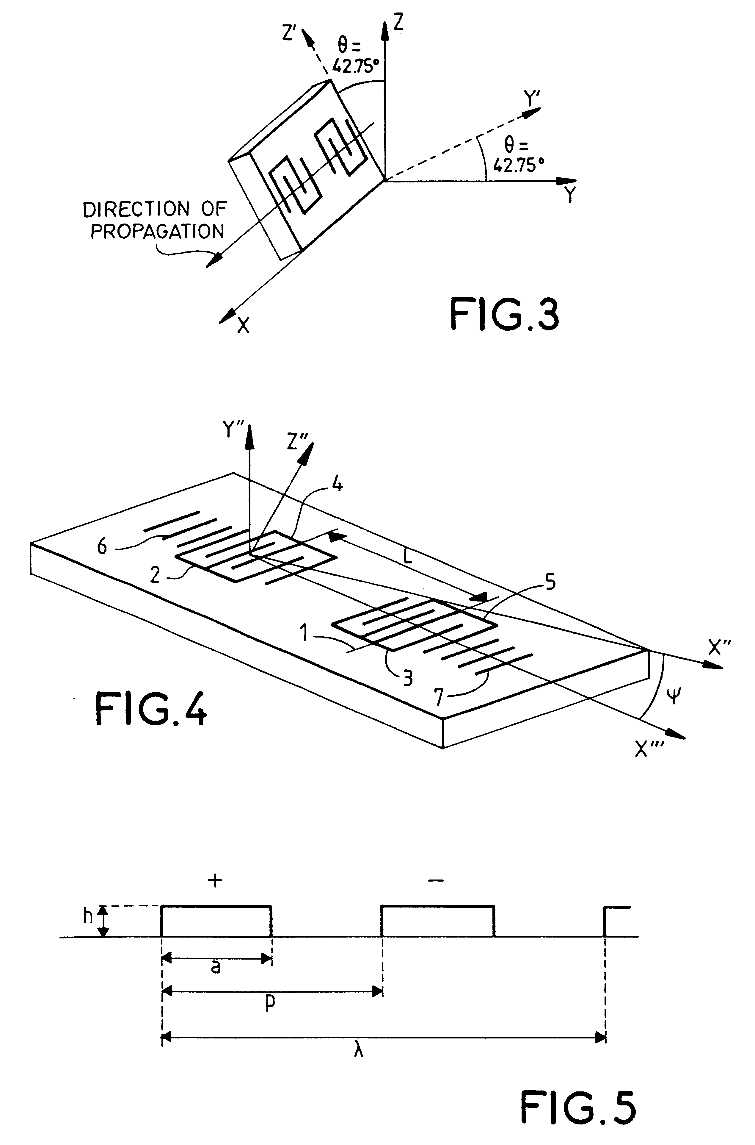
FIG. 4 gives a very schematic view of an exemplary surface acoustic wave device according to the invention. The device comprises transduction centers and reflection centers made by means of metallic electrodes. More specifically, this device has two interdigitated electrode transducers 2, 3, 4 and 5 and two reflectors 6 and 7 formed by gratings of lines. The direction of propagation is the direction X'" of the substrate after rotation and is therefore the axis X" of the cutting plane defined by the angles .phi. and .theta. rotated by an angle .psi..

For each cutting plane defining a given quartz substrate, there is a preferred direction of propagation of the surface acoustic waves for which the performance characteristics of the device are optimized.

This direction of propagation is defined by the angle .PSI.:

According to the invention .PSI.=35.degree.+10.degree. (sin (3.phi.)).

Here below, for different directions of cutting planes and directions of propagation of the acoustic waves, ...


PUM


Abstract

A low-loss surface acoustic wave filter on a quartz substrate with optimized cutting. A range of cutting angles and directions of propagation of the waves on the quartz substrate are defined, making it possible to obtain high coefficients of reflection of the electrodes used in the filter. The range of cutting angles and directions of propagation of the waves are decisive factors for the making of the filter.

Description

1. Field of the InventionThe field of the invention is that of acoustic wave devices and specially that of filters or resonators made on the surface of a substrate made of piezoelectric material.The material used for making a surface acoustic wave device and the cut of the material are generally chosen on the basis of two criteria: the piezoelectric coupling coefficient that characterizes the maximum relative band that can be obtained and the behavior of the material as a function of the temperature. Indeed, when the temperature rises, the material expands and its coefficients of elasticity vary, giving rise to variations in the speed of propagation of the surface wave and hence in the frequency of the devices.2. Description of the Prior ArtQuartz is a material that has long been used for surface acoustic wave filters. The cut generally used is what is called the ST cut (M B. Schultz, B. J. Matzinger, M. G. Holland, "Temperature Dependence of Surface Acoustic Wave Velocity on .alpha...

Claims


Application Information

Patent Timeline
Patent Type & Authority Patents(United States)
IPC IPC(8): H03H9/02H03H9/25H03H9/145H03H9/215
CPCH03H9/02551H03H9/215
Inventor BALLANDRAS, SYLVAINSOLAL, MARCBRIOT, EMMANUELLE
Owner SNAPTRACK
Why Eureka
Try Eureka