Acoustic touch sensor

a touch sensor and acoustic technology, applied in the field of acoustic contact detection devices, can solve the problems of unguarded piezoelectric transducers, inability to fully adapt the touch panel of ultrasonic methods to the flat panel, and no space available for wedge transducers, etc., to achieve smooth fabrication and high reliability

Inactive Publication Date: 2007-03-06
TOUCH PANEL SYST
View PDF31 Cites 65 Cited by
  • Summary
  • Abstract
  • Description
  • Claims
  • Application Information

AI Technical Summary

Benefits of technology

[0013]The inventors has dedicated themselves to the research in order to solve the above problems and accomplish the present invention based on the finding that if a planar wiring using conductive paste is used for an electrical connection with a piezoelectric vibrator, the wirin

Problems solved by technology

Although such an edge transducer is small in size, the exposed piezoelectric transducer remains unguarded.
However, when the display is formed by a flat panel such as a liquid-crystal display or a plasma display, there is no gap left between the panel and the outer frame in the peripheral region of the panel surface covered with the outer frame and thus no space is available for accommodating the wedge transducer.
Accordingly, with the wedge transducer, the touch panel of the ultrasonic method is not fully adaptable to the flat panel.
Especially, when the wedge transducer is employed in an acoustic touch sensor using the Rayleigh wave, there could be a fear that the mechanical designing may become complicated, thereby limiting the options.
If a touch panel of the ultrasonic elastic surface wave method is applied to the LCD, there would be a problem arisen in association with a cable to be used for tra

Method used


Image

  • Acoustic touch sensor
  • Acoustic touch sensor
  • Acoustic touch sensor

Examples


example 1

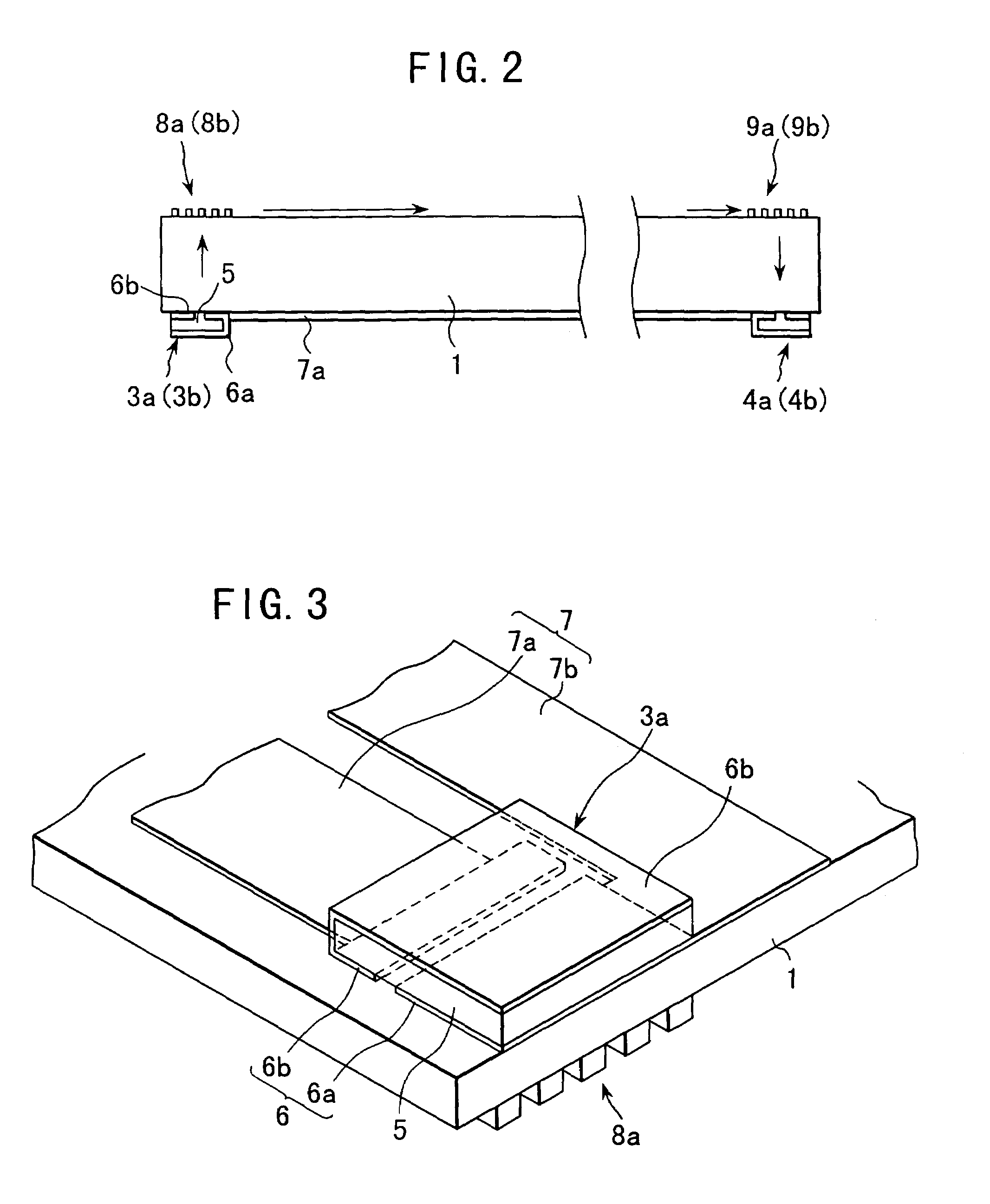
[0055]A pattern shown in FIG. 3 was printed on a back surface of a substrate made of soda-lime glass by the screen printing method with silver paste used as an ink. After the printing, the object was heated and thus dried in an oven at 120° C. for 10 minutes.

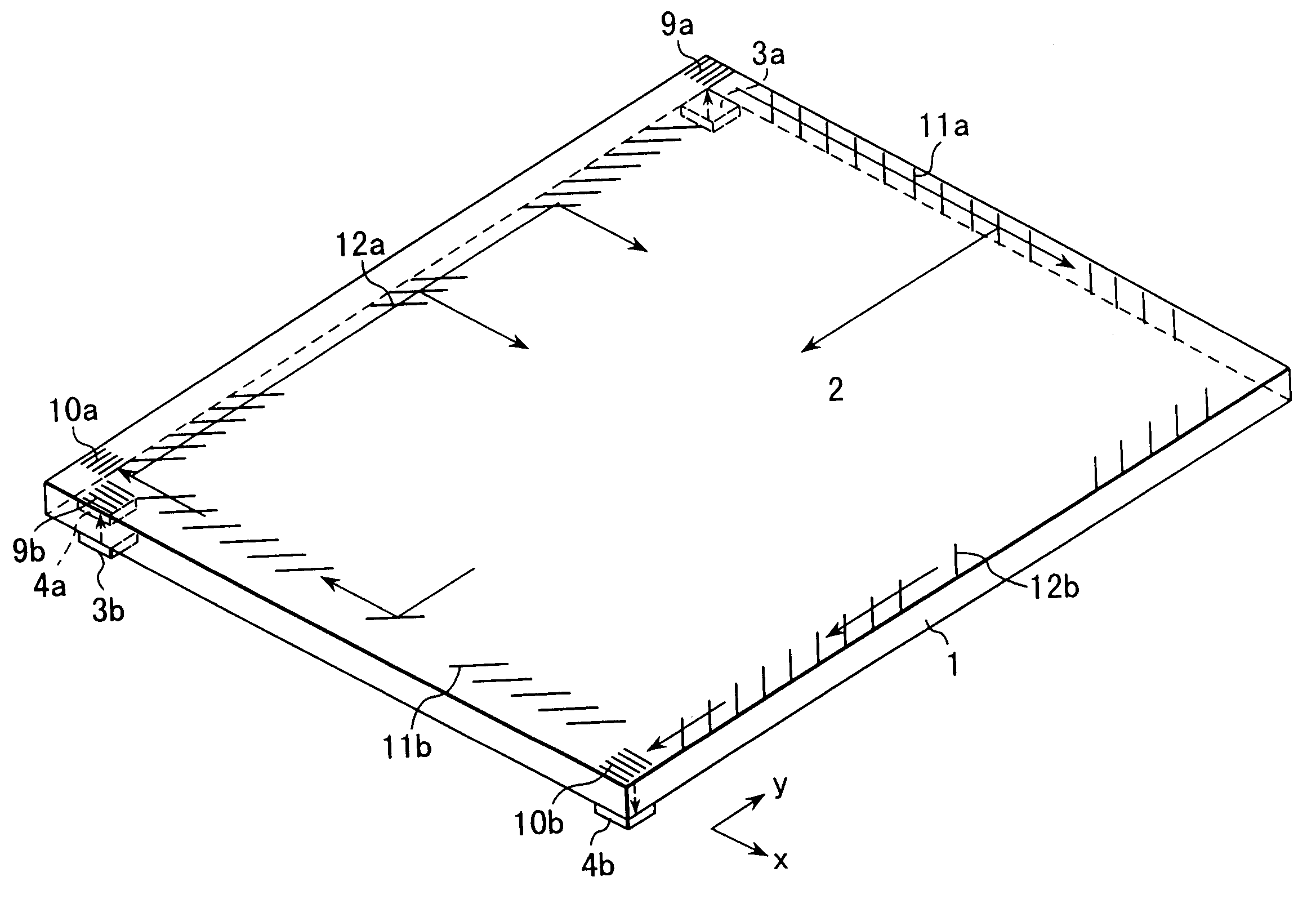
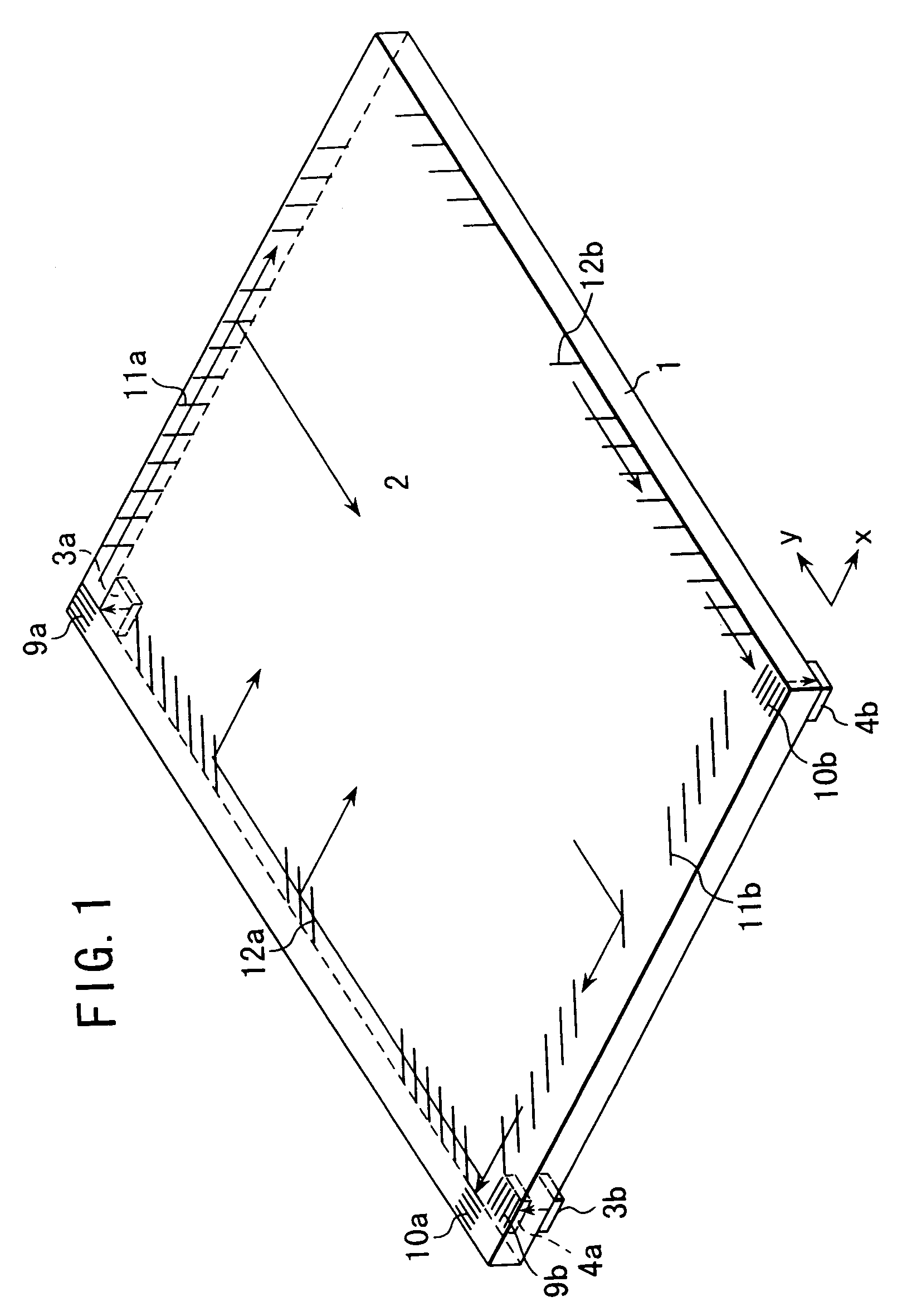
[0056]Subsequently, as shown in FIG. 1, an acoustic mode coupler (a grating transducer) and a reflective array were printed on a top surface of the substrate by the screen printing method with glass paste used as an ink and then dried.

[0057]Then, the printed pattern together with the glass substrate was baked at a baking temperature in a range of 485° C. to 490° C. with the top keeping period of 10 minutes, and thus the glass substrate with a planar wiring was obtained. It is to be noticed that the height of the grating of the grating transducer is 40 μm and the reflective array element is angled at 45° with respect to the X-axis and the Y-axis.

[0058]A plate-like piezoelectric vibrator was bonded onto the obtained glass substrat...

example 2

[0059]A pattern shown in FIG. 3 was printed on a polypropylene film fixedly attached onto a substrate, by the screen printing method with silver paste used as an ink. After the printing, the object was heated and thus dried in an oven at 120° C. for 10 minutes.

[0060]Subsequently, as shown in FIG. 1, an acoustic mode coupler (a grating transducer) and a reflective array were printed on a top surface of the substrate by the screen printing method with glass paste used as an ink and then dried. It is to be noticed that the height of the grating of the grating transducer is 40 μm and the reflective array element is angled at 45° with respect to the X-axis and the Y-axis.

[0061]The polypropylene film was tightly contacted to a back surface of the glass substrate and a film having a predetermined pattern printed thereon was further loaded thereon, and then the printed pattern together with the glass substrate was baked at the baking temperature in a range of 485° C. to 490° C. with the top...


PUM


Abstract

A coordinate input device of touch-type capable of giving an electric signal to a transducer, even if said transducer is disposed on a back surface of a substrate. The device contains acoustic wave transducers (piezoelectric vibrators), each functioning for oscillating a bulk wave (a first wave) toward a top surface of a substrate; a planar wiring formed on a back surface of the substrate by, e.g., transfer printing with conductive paste, for supplying the piezoelectric vibrator with electric power; diffractive acoustic wave mode couplers, each functioning for converting said bulk wave into a surface acoustic wave (a second wave) and vice versa; and a detector to detect scatter in the surface acoustic wave on the top surface of the substrate. Employing the planar wiring allows the wiring to be disposed even on the back surface of the substrate and also it may resolve the problem of fragility associated with a cable wiring.

Description

FIELD OF THE TECHNOLOGY[0001]The present invention relates to an acoustic contact detecting device or a coordinate input device of touch-type, such as a touch panel of an ultrasonic method, for acoustically detecting a contact point and also to a substrate for the same device.DESCRIPTION OF THE PRIOR ART[0002]A touch panel has been used broadly as an input device for an interactive computer system in various applications including a kiosk information terminal or an order input system at a restaurant. A known typical touch panel includes a touch panel of a resistive film method, a touch panel of an electrostatic capacity method and a touch panel of an acoustic method. The touch panel of the acoustic method, especially an ultrasonic touch panel, is distinctively advantageous if a highly robust contact sensing face and / or an improved transmittance of a display image is required.[0003]A variety of transducers (especially, wedge transducers) have been used to connect or couple a piezoele...

Claims


Application Information

Patent Timeline
IPC IPC(8): G09G5/00G06F3/043G01B17/00G06F3/041
CPCG06F3/0436
Inventor KANBARA, SHIGEKIKANEDA, HIROSHIKAMON, KEIICHI
Owner TOUCH PANEL SYST
Why Eureka
Try Eureka