Liquid crystal display panel

a technology liquid crystal, which is applied in the field of liquid crystal display panel, can solve the problems of increasing power consumption, wasting the majority of light emitted by light sources, and very large area of a region (background part) other than the area of the information display par

Inactive Publication Date: 2001-11-13
CITIZEN WATCH CO LTD
View PDF18 Cites 13 Cited by
  • Summary
  • Abstract
  • Description
  • Claims
  • Application Information

AI Technical Summary

Benefits of technology

Accordingly, even with a light source having a smaller quantity of light emission than that in the case of the conventional liquid crystal display panel, bright display with sufficient visibility can be executed. As a result, the life of a battery can be prolonged due to reduction in consumption of power supplied by the battery.
Further, by stalling a non-reflection layer on the visible side of the first polarizing film, a quantity of light reflected by the first polarizing film can be held down at a low level even at locations such as the outdoors at daytime, and so forth, where an intense external light falls, maintaining excellent visibility.
In such a case, therefore, display of information can be executed with the use of reflected external light only by turning off the power supply to the light source, achieving significant savings in consumption of a battery in use.
Further, by use of a color polarizing film for the second polarizing film, or by installing a color filter between the light source and the second polarizing film, parts for display in white can be indicated in colors differing from the color of light emitted by the light source, enabling a display of information which is highly variable in the tone of color to be effected.
By installing the transflective reflector film between the light source and the second polarizing film, and further, the color filter between the transflective reflector film and the light source, it becomes possible to change the tone of color of the display executed with the use of external light from that using light emitted from the light source, enabling the display highly variable in the tone of color to be effected.

Problems solved by technology

However, in the case of displaying digital information of time and so forth in the liquid crystal display panel, the area of a region (background part) other than the area of the information display part is very large.
Accordingly, most of the light emitted by the light source is wasted.
Accordingly, it is necessary to increase the amount of luminescence to display with high visual recognition, leading to an increase of the power consumption, causing a problem of shortening the life span of a battery, in the case of portable electronic equipment.
Further, in the panel merely indicating digital display of time information and calendar information in white against the black background, variation in design cannot be offered, with a tendency to quickly lose popularity among consumers.
Probably as a result, consumption of digital watches has recently been on the decline.
Similarly, in the case of transmission display by the light source incorporated therein with the conventional liquid crystal display panel used in other electronic equipment, various information expressed in letters and graphics is generally displayed in white against the black background, and although there are some wherein information can be displayed in black against the white background in an inverse mode, the liquid crystal display panel has been found still lacking in design variation and sense of amusement.
With the liquid crystal display panel as shown in FIG. 1, therefore, at a location such as the outdoors in fine weather, where a very intense external light falls, a half of the external light falling on the first polarizing film 2 is reflected toward the visible side with the possible result that contrast between parts displayed in white by light transmitted from the light source 4, and the background part as well as parts displayed in black is caused to deteriorate, causing the display to become difficult to see for a viewer.

Method used


Image

  • Liquid crystal display panel
  • Liquid crystal display panel
  • Liquid crystal display panel

Examples


case 20

the wrist watch is assembled with a glass 22 and a case back 23, integrally joined with a case body 21 made of metal.

The glass 22 is made of a transparent material such as sapphire glass, tempered glass, or plastic, and is integrally joined with the front face of the case body 21 by means of direct bonding, or fitting therein via a packing. The case back 23 is integrally joined with the back face of the case body 21 by means of screwing therein or fitting therein via a packing. Thus, the case 20 has an airtight inner structure so as not to allow ingress of dust or moisture.

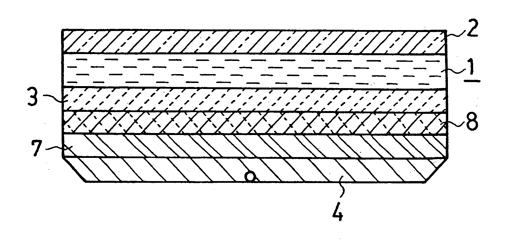
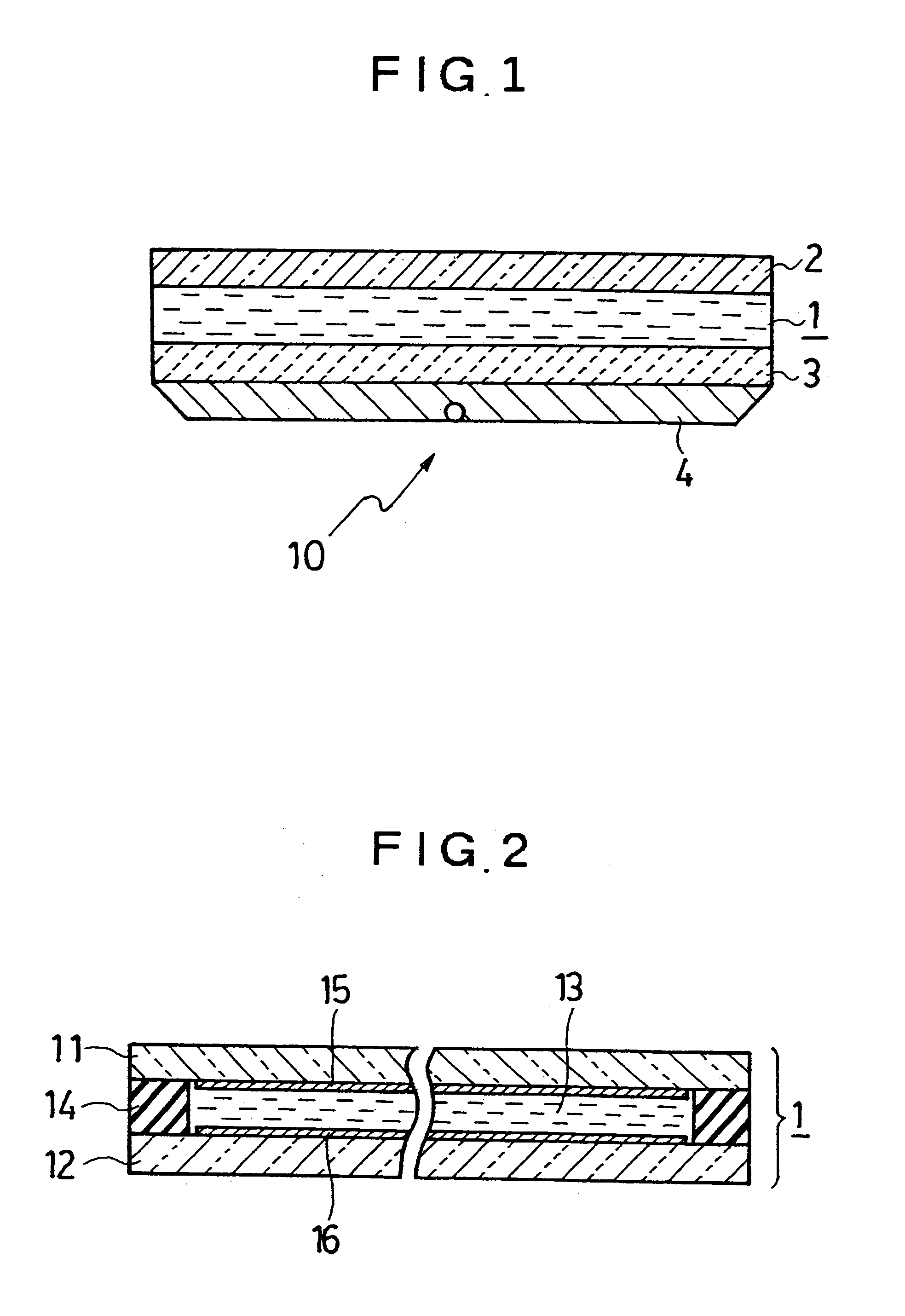
A liquid crystal display panel (liquid crystal display device) 10 according to the invention to serve as a display for indicating time and so forth is installed on the side of the glass 22 inside the case 20.

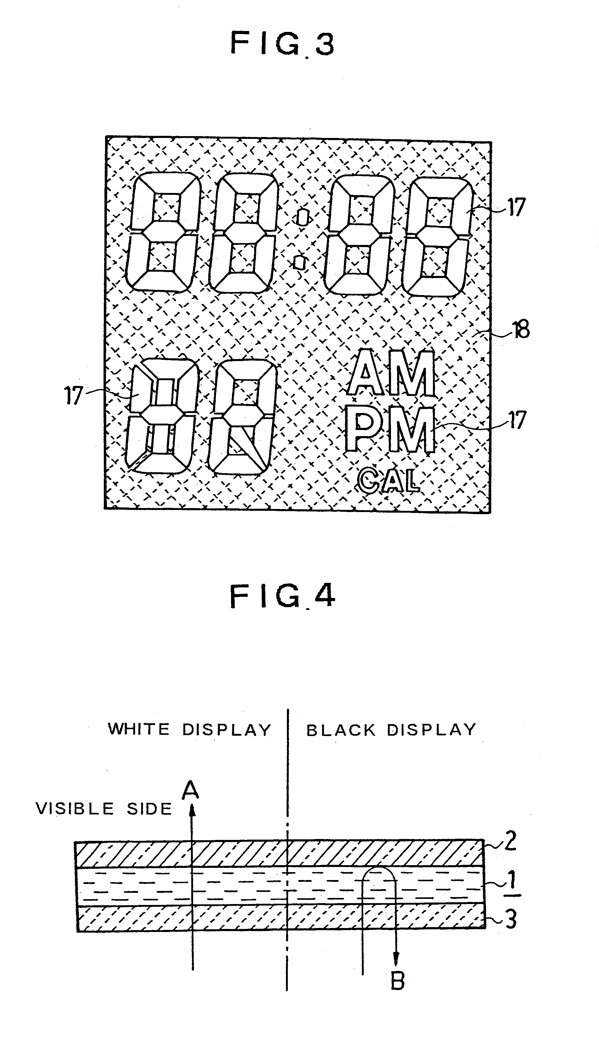
The liquid crystal display panel 10 comprises a time display section 10a for displaying hour, minute, and second, a calendar display section 10b for displaying month, date, days of the week, and a colon mark d...


PUM

PropertyMeasurementUnit
twist angleaaaaaaaaaa
oscillation frequencyaaaaaaaaaa

Abstract

A liquid crystal display panel comprising a liquid crystal cell with liquid crystals sealed therein, sandwiched between two transparent substrates having an electrode on each of the inner surfaces thereof facing each other, a first polarizing film disposed on the visible side of the liquid crystal cell, a second polarizing film disposed on the opposite side of the liquid crystal cell from the visible side, and a light absorbing film disposed on the opposite side of the second polarizing film from the visible side. The first polarizing film is a reflection-type polarizing film reflecting the light linearly polarized in the direction orthogonal to the transmission axis thereof, and the second polarizing film is an absorption-type polarizing film or color polarizing film each absorbing the light linearly polarized in the direction orthogonal to the transmission axis thereof. A transflective reflector and / or a color filter may preferably be disposed between the second polarizing film and a light source.

Description

The invention relates to a liquid crystal display panel used in various electronic equipment such as timepieces (watches and clocks), portable information equipment, and so forth for indicating time information, calendar information and other various information.BACKGROUND TECHNOLOGYA timepiece for indicating digital display of time information such as hour, minute, and second, and calendar information such as date, days of the week, month, and year, by use of a liquid crystal display panel (device), has been in widespread use for watches and clocks, provided with a crystal oscillation circuit.There has also been in use a combination watch wherein analog display indicating time information by the hands of the watch is used in combination with digital display indicating time information and calendar information in numbers and letters.Further, there has been proposed an analog watch for selectively displaying scales in various patterns, or for displaying simulated hands for an hour ha...

Claims


Application Information

Patent Timeline
Patent Type & Authority Patents(United States)
IPC IPC(8): G02F1/1335G02F1/13G04G9/00
CPCG02F1/133536G04G9/0035G02F1/133533G02F2001/133545G02F1/133545G02F1/1335
Inventor HOSHINO, KOICHI
Owner CITIZEN WATCH CO LTD
Why Eureka
Try Eureka