
Remote installation and removal tool for video surveillance camera assembly

a technology for video surveillance and removal tools, which is applied in the direction of wrenches, manufacturing tools, television systems, etc., can solve the problems of individuals who do not adapt to performing tasks easily, and can be difficult to achieve the effect of reducing the risk of individuals being injured

Inactive Publication Date: 2001-11-20
SENSORMATIC ELECTRONICS CORP
View PDF6 Cites 36 Cited by
  • Summary
  • Abstract
  • Description
  • Claims
  • Application Information

AI Technical Summary

Benefits of technology

According to an aspect of the invention, there is provided a tool for removing a surveillance camera assembly housing from a base on which the assembly is mounted, including a pole portion, and a camera assembly housing engagement portion mounted on the pole portion, and the engagement portion including structure for engaging the camera assembly housing at a plurality of points on the peripheral surface of the assembly housing, the engagement portion being formed as a single unitary body. Further in accordance with this aspect of the invention, the engagement portion may be generally in the shape of a hollow cylinder in which the camera assembly housing is contained when the housing is engaged by the engagement portion. The engagement portion may include a plurality of slots formed in the cylinder, each for engaging a respective rib which projects outwardly from the peripheral surface of the camera assembly housing. Preferably, the engagement portion is mounted on the pole portion in a manner which prevents rotation and pivoting of the engagement portion relative to the pole portion.

Problems solved by technology

However, removable of this known type of camera dome from the structure on which it is installed requires the individual assigned to perform the removal to disengage the spring-loaded rods by hand from the mounting bracket, usually while standing on a ladder or on scaffolding or the like.
Neither removal nor installation of the prior art camera dome can be considered easy or convenient, and either operation may entail some risk for individuals who do not adapt easily to performing tasks while standing on a ladder or scaffold.

Method used


Image

  • Remote installation and removal tool for video surveillance camera assembly
  • Remote installation and removal tool for video surveillance camera assembly
  • Remote installation and removal tool for video surveillance camera assembly

Examples


Embodiment Construction

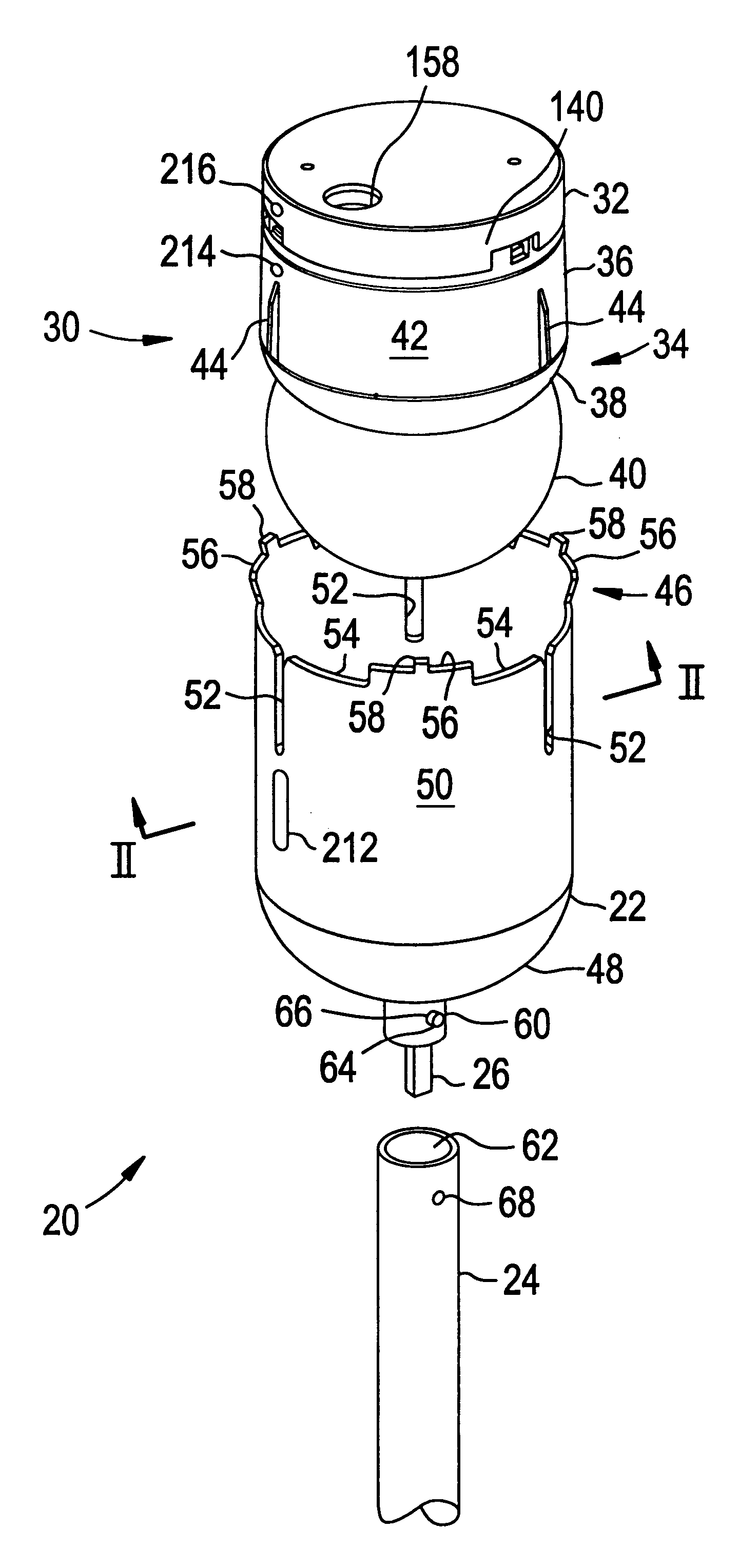
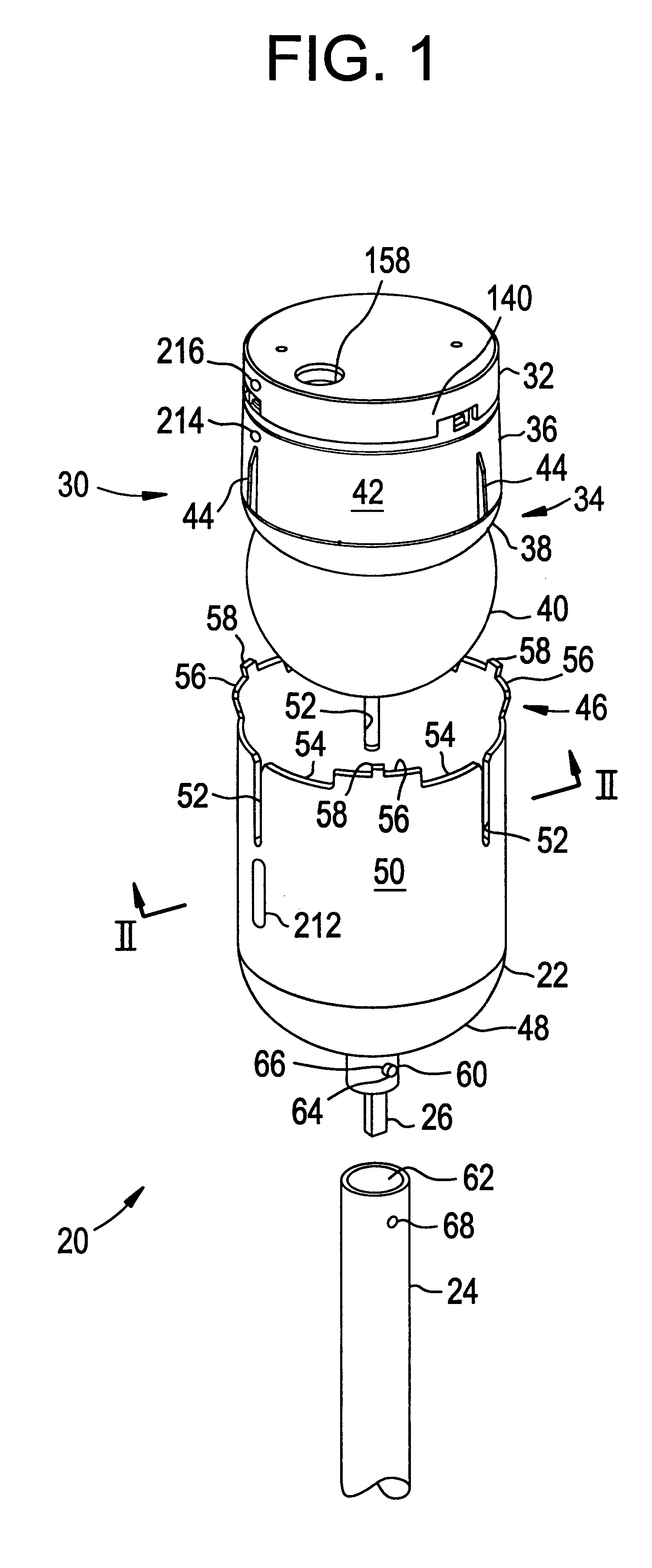
An embodiment of the invention will now be described, initially with reference to FIG. 1.

Reference numeral 20 in FIG. 1 generally indicates a dome installation and removal tool provided in accordance with the invention. The tool 20 is made up of a head portion 22 and a pole portion 24 to which the head portion 22 is selectively mountable by means of mounting portion 26.

Also shown in FIG. 1 is a video surveillance camera dome assembly 30. The dome assembly 30 is made up of a base 32 which is adapted to be permanently mounted on a ceiling or other support structure, and an assembly housing 34 which is adapted to be removably mounted to the base 32. The housing 34, in turn, includes a generally cylindrical main body 36, a skirt 38, and a generally spherical dome portion 40. The body portion 36 of the assembly housing 34 has an external or peripheral surface 42 on which vertically extending ribs 44 are formed. Preferably, the number of ribs is three in all, and the ribs are arranged at ...


PUM


Abstract

A surveillance camera assembly housing is releasably locked to a base for the housing. The base is installed on a ceiling or at another location remote from ground level. A removal tool head, in the form of a hollow cylinder, is provided at the end of a pole. Slots formed in the tool head engage ridges on the camera assembly housing. The assembly housing is twisted to release it from the base and then is brought to ground level while contained within the tool head.

Description

This invention is concerned with video surveillance camera mounting assemblies, and with methods of, and tools for, installing video surveillance cameras and removing installed cameras.It is well known to provide mounting structures for video cameras to be installed in or near buildings to be protected by a video surveillance system. The mounting structures typically include a housing that is secured to the ceiling of the building or at another suitable location on the building. The housing contains a video camera, motors and other components which permit the camera to be moved by remote control through a range of motion, and electronics for receiving control signals and transmitting video signals generated by the camera. Frequently, a portion of the enclosure is in the shape of a dome and is formed of plastic which permits incident light to enter and be captured by the video camera. The assembly, including the housing, the camera, and associated components, is commonly referred to ...

Claims


Application Information

Patent Timeline
Patent Type & Authority Patents(United States)
IPC IPC(8): B25B13/00B25B13/48B25B27/14
CPCB25B13/48B25B27/14
Inventor YAP, WALTER N.PEREZ, SERGIO M.ANDERSON, LUIS E.HANEY, DAVID A.
Owner SENSORMATIC ELECTRONICS CORP
Features
  • Generate Ideas
  • Intellectual Property
  • Life Sciences
  • Materials
  • Tech Scout
  • Unparalleled Data Quality
  • Higher Quality Content
  • 60% Fewer Hallucinations
Learn More