Laser device

Inactive Publication Date: 2001-11-20
SEC OF DEFENCE IN HER BRITANNIC MAJESTYS GOVERNMENT OF THE UK OF GREAT BRITAIN & NORTHERN IRELAND THE +1
View PDF14 Cites 52 Cited by
  • Summary
  • Abstract
  • Description
  • Claims
  • Application Information

AI Technical Summary

Problems solved by technology

Attempts have been made to obtain broader spectral bandwidth output using dye or vibronic laser systems, but the dyes used in dye systems may be harmful a

Method used


Image

  • Laser device
  • Laser device
  • Laser device

Examples


Embodiment Construction

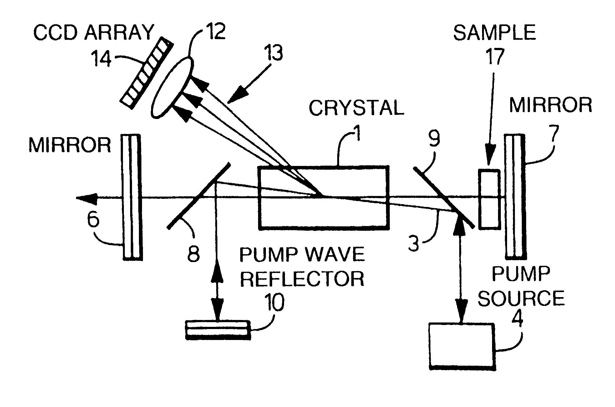
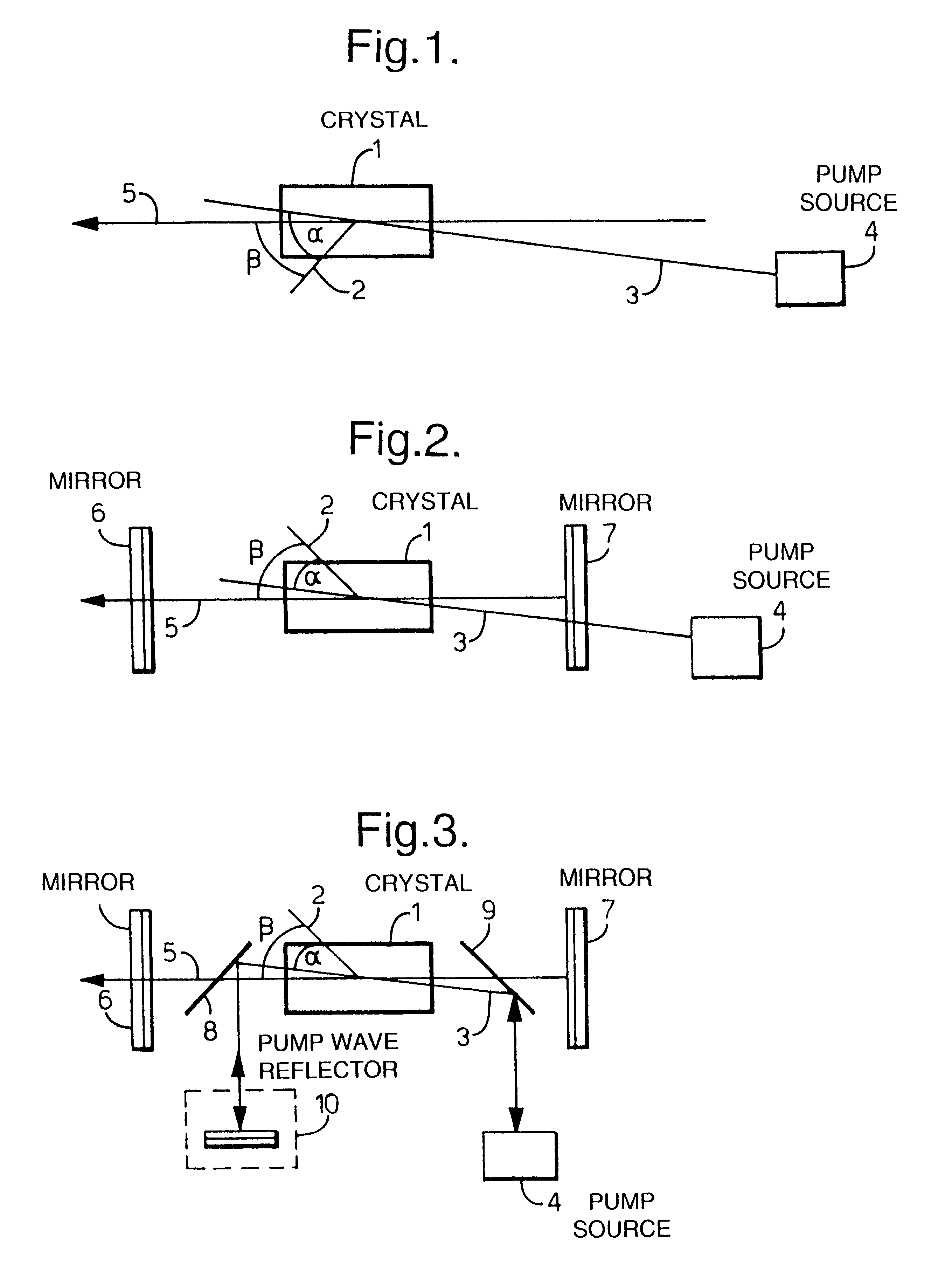
FIG. 1 illustrates a first example of a laser device according to the invention. The device comprises an optical parametric generator (OPG) formed of a non-linear crystal 1 in which an optic axis 2 is defined. A pump wave 3 is input from a pump source 4 and exits from the crystal 1 at an angle a to the optic axis 2. A generated wave 5 exits the crystal at an angle .beta. to the optic axis 2. In FIG. 2 a pair of mirrors 6,7 are provided which define a standing wave resonator for the generated signal wave 5, the resonant wave in this case, so forming an optical parametric oscillator (OPO). Alternatively, with an additional mirror, the mirrors 6,7 could form a ring cavity.

The pump wave 3 may enter either through or around the mirrors 6,7 or, as illustrated in FIG. 3, via a pair of reflectors 8,9 which couple the pump wave 3 from the pump source 4 into the crystal 1. Typically, these reflectors are dichroic mirrors, so that only the pump wave is reflected and the signal wave passes thro...


PUM


Abstract

A laser device comprises a non-collinear optical parametric generator (OPG) and a pump wave source (4). The OFG comprises a non-linear crystal (1) fixedly mounted within the generator wherein the relative orientations of the pump wave (3) and each generated wave (5) to an optic axis (2) of the non-linear crystal (1) are substantially such that a point of inflexion is produced in a tuning curve of wavelength versus pump wave orientation of one of the generated waves, such that a broadband spectral output is obtained. This device has many applications including an amplifier for an input seed wave in which the crystal dose not have to be rotated to match the wavelength of the seed wave; or as part of a continuously tuneable narrowband source.

Description

1. Field of the InventionThis invention relates to a laser device.2. Discussion of Prior ArtOptical parametric generator's (OPG's) have been used to generate laser-like output within a certain spectral range. The OPG comprises a non-linear crystal material to which a pump source is applied. The spectral range is constrained by the pump source wavelength, the type of non-linear material used and the relevant geometry-type implemented. The output of an OPG is usually of relatively narrow spectral bandwidth, centred at a wavelength determined by the angle of the crystal axis relative to the pump to axis. Conventionally, the centre wavelength can be continuously tuned by altering the orientation or changing the temperature of the crystal, tuning taking place through consideration of the principle of conservation of momentum, namely phase matching in the terminology of non-linear optics. Normally, for a certain orientation of the crystal, only a narrow spectral range of signal and idler ...

Claims


Application Information

Patent Timeline
IPC IPC(8): G01N21/47G02F1/35G02F1/39H01S3/108
CPCG01N21/4795G02F1/39
Inventor DAWBER, WILLIAMWANG, JIANDUNN, MALCOLM HRAE, CAMERON F
Owner SEC OF DEFENCE IN HER BRITANNIC MAJESTYS GOVERNMENT OF THE UK OF GREAT BRITAIN & NORTHERN IRELAND THE
Why Eureka
Try Eureka