Interpaper spacing control in a media handling system
- Summary
- Abstract
- Description
- Claims
- Application Information
AI Technical Summary
Problems solved by technology
Method used
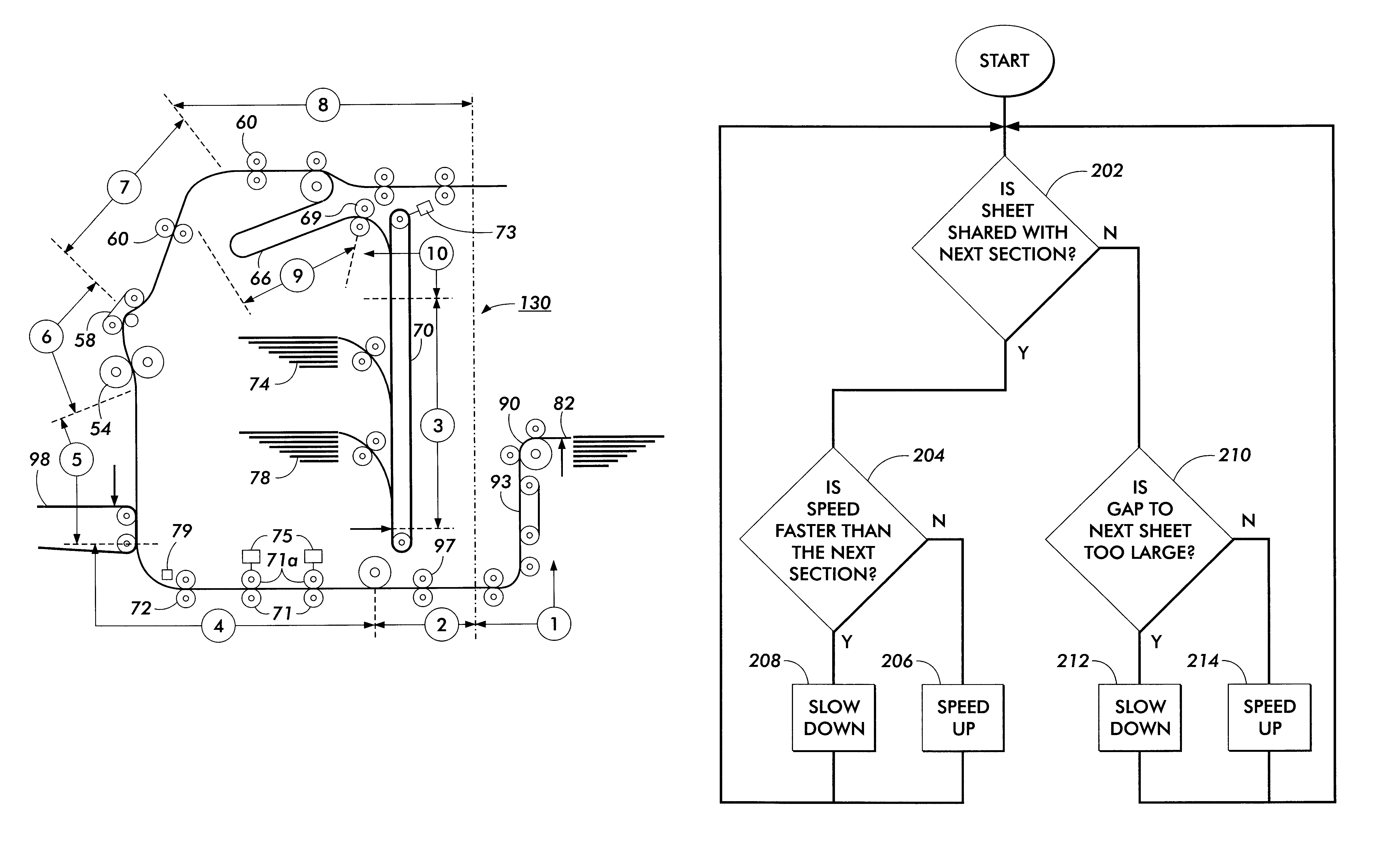
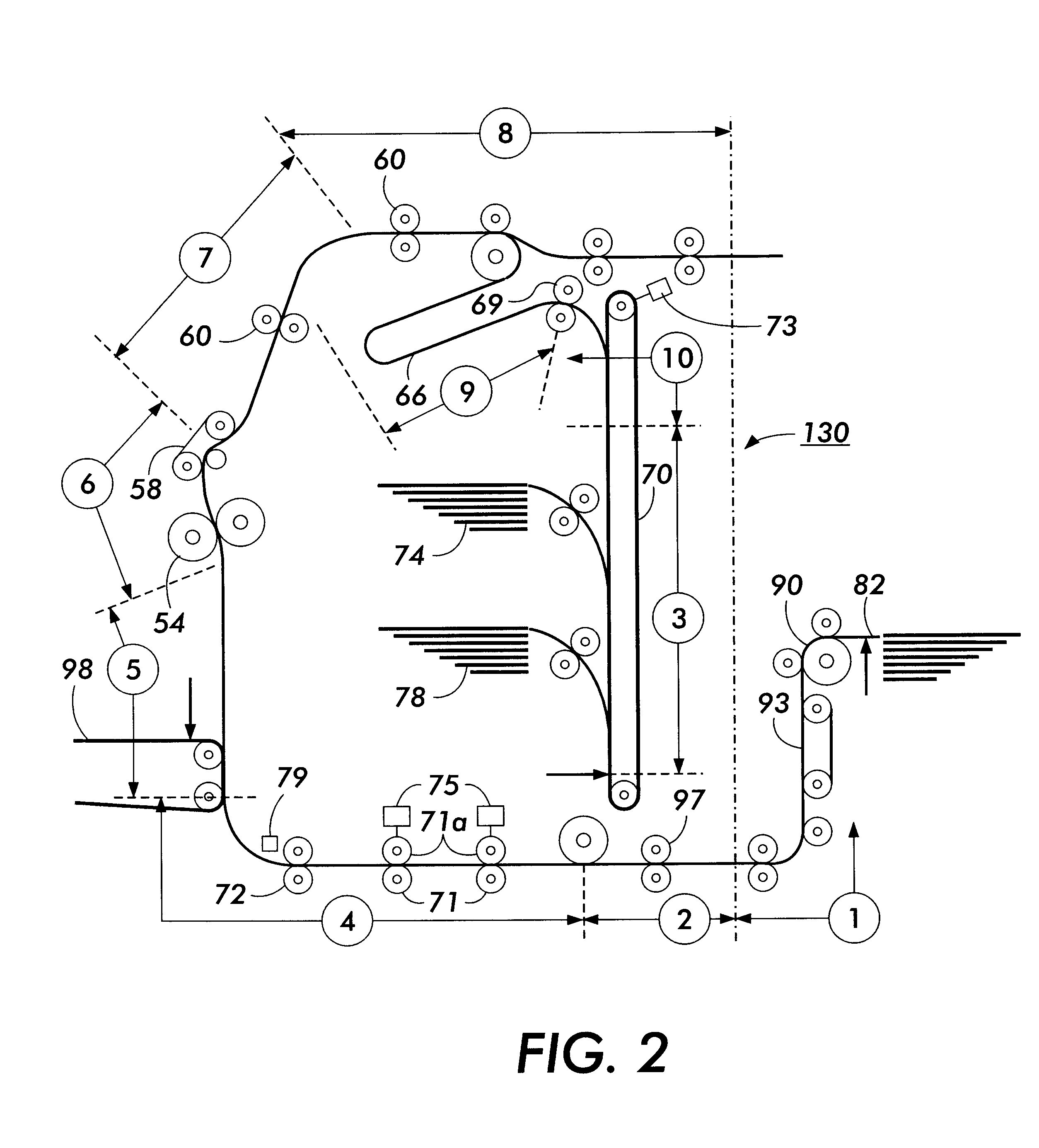
Image

Examples
Embodiment Construction
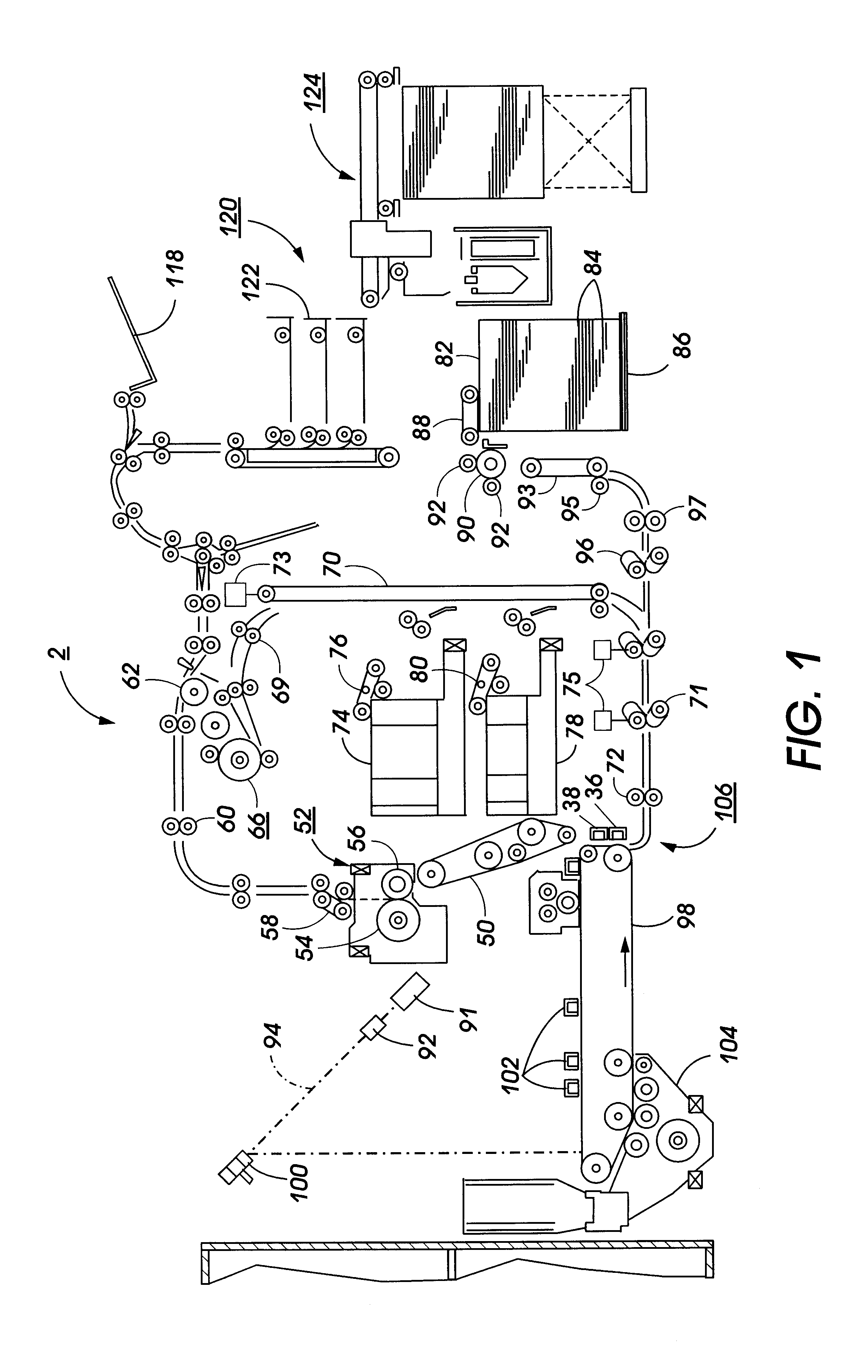
Referring to FIG. 1, there is shown an exemplary laser based printing system 2 for processing print jobs in accordance with the teachings of the present invention. Printing system 2 for purposes of explanation is divided into a controller section and a printer section. While a specific printing system is shown and described, the present invention may be used with other types of printing systems such as ink jet, ionographic, etc.
The printer section comprises a laser type printer and for purposes of explanation is separated into a Raster Output Scanner (ROS) section, Print Module Section, Paper Supply Section, and Finisher. The ROS has a laser 91, the beam of which is split into two imaging beams 94. Each beam 94 is modulated in accordance with the content of an image signal input by acousto-optic modulator 92 to provide dual imaging beam 94. Beams 94 are scanned across a moving photoreceptor 98 of the Print Module by the mirrored facets of a rotating polygon 100 to expose two image l...
PUM
| Property | Measurement | Unit |
|---|---|---|
| Speed | aaaaa | aaaaa |
Abstract
Description
Claims
Application Information