Rapid fabric forming for penetration resistant fabric

a technology of penetration resistance fabric and rapid forming, which is applied in the field of textile fabrics, can solve the problems of limiting the number of yarns that can be placed in a given area, affecting the structural damage of individual yarns, and affecting the stability of the fabri

Inactive Publication Date: 2001-11-27
EI DU PONT DE NEMOURS & CO
View PDF33 Cites 48 Cited by
  • Summary
  • Abstract
  • Description
  • Claims
  • Application Information

AI Technical Summary

Problems solved by technology

In a process using weaving to hold the strands together, the strands are guided over and under adjacent strands which is a slow process and one that does not permit much variety in forming the fabric unless complex weaving patterns and complex machines are used.
The yarns are shifted over one another and are forced tightly into position which often causes structural damage to the individual yarns.
Coated yarns exhibiting high friction against other yarns cannot be readily woven.
For a given weaving process (machine) and yarn denier there is a limit to the number of yarns that can be placed in a given area for a single layer since the yarns cannot readily be overlapped.
It will be appreciated that since the yarns are flexible, if untensioned they will bend over and under one another in the structure and collapse to about a two-to-four yarn thickness so it will be difficult to pull unbonded yarns from the structure.
In some fabrics, there may be highly variable or very large cell repeats and it may not be useful to designate a cell; the entire fabric may be referred to as a cell.
In this case flexibility of the fabric is still retained due to the thinness of the fabric, but the inherent flexibility of the yarn before bonding is diminished.
In the case of a penetration resistant fabric, however, bulk and flexibility may be compromised to prevent yarn shifting which cannot be tolerated.
Too few connections and fabric integrity is compromised; too many connections and the fabric flexibility is compromised and bulk is reduced.

Method used


Image

  • Rapid fabric forming for penetration resistant fabric
  • Rapid fabric forming for penetration resistant fabric
  • Rapid fabric forming for penetration resistant fabric

Examples


example 2

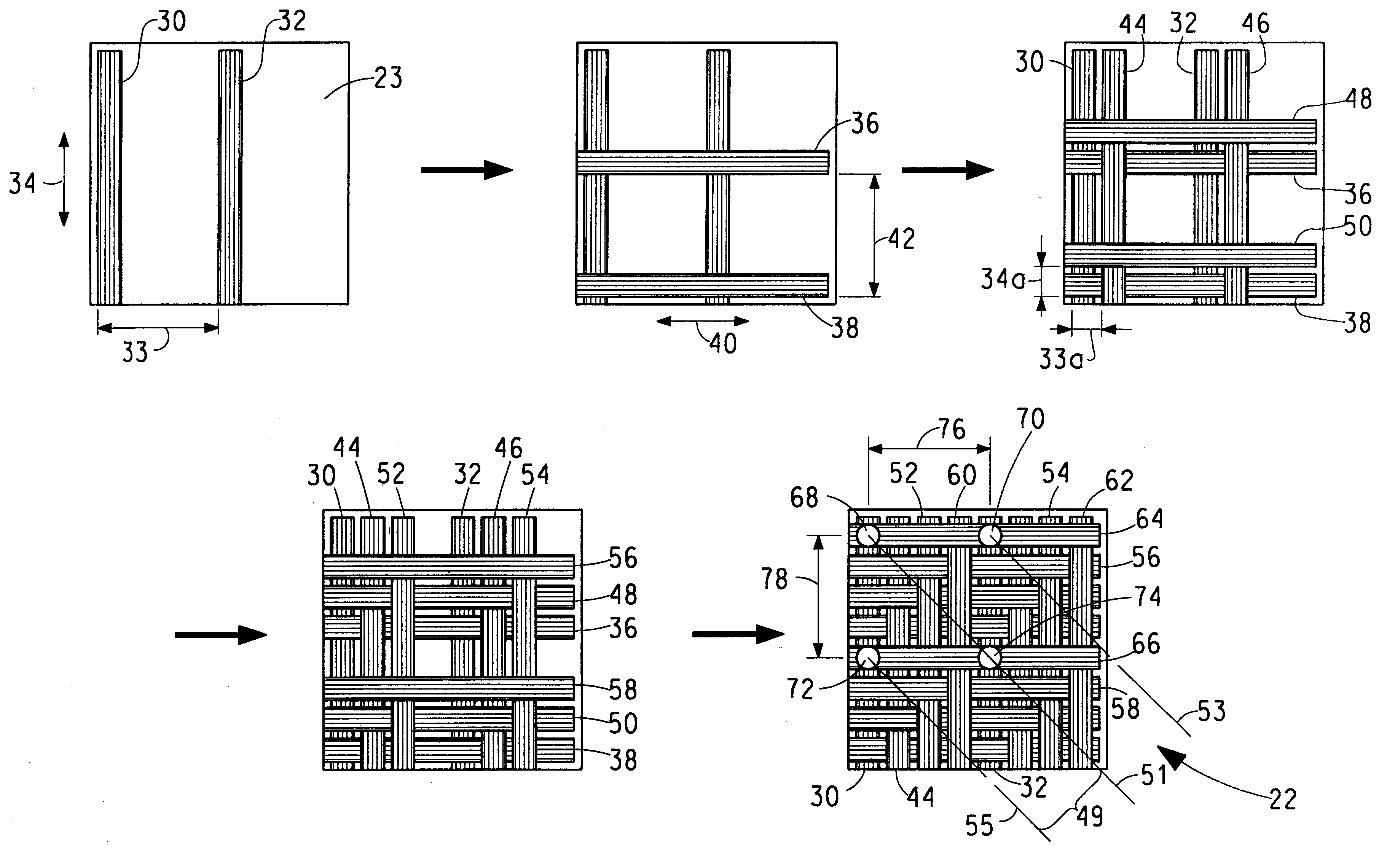
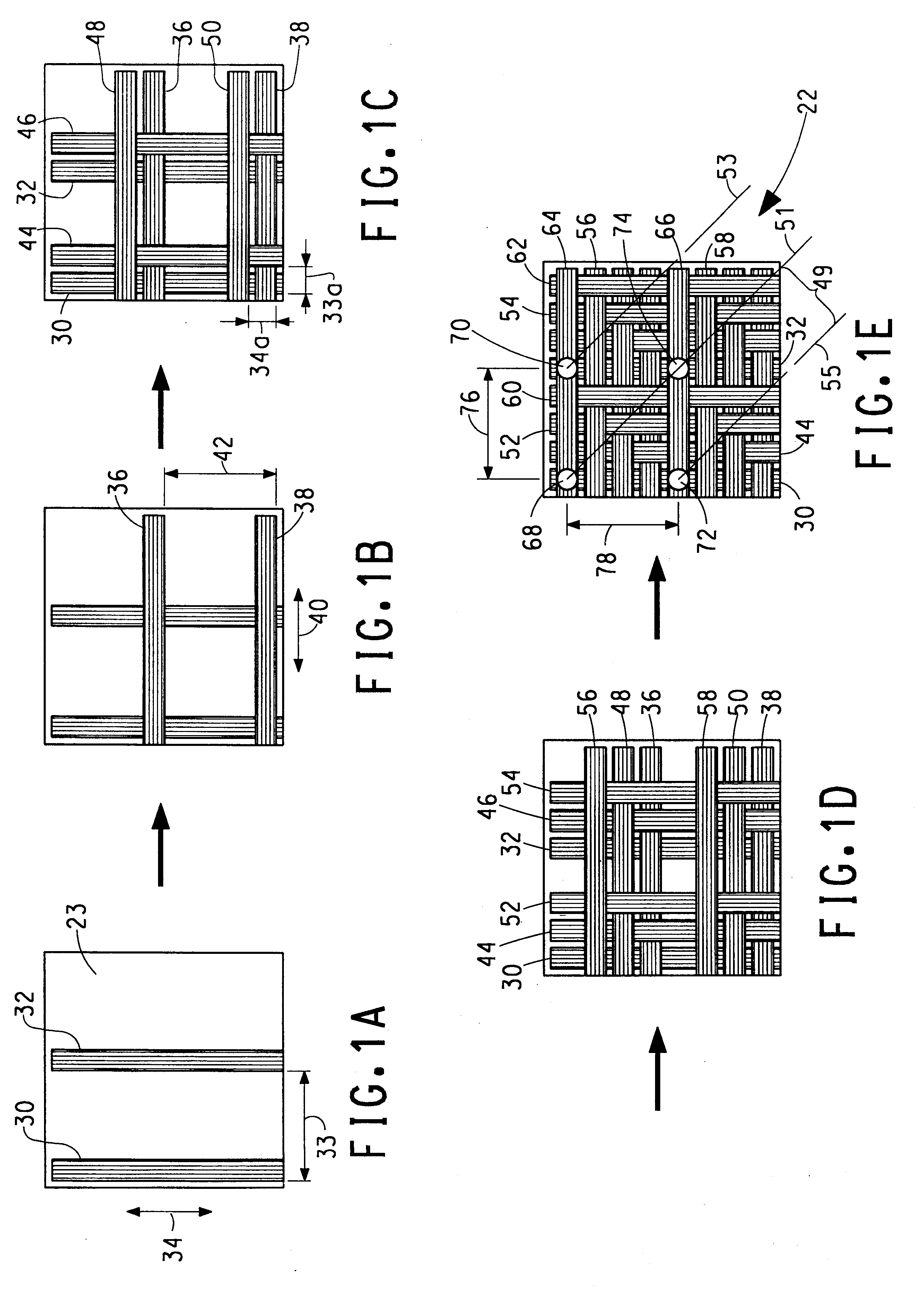
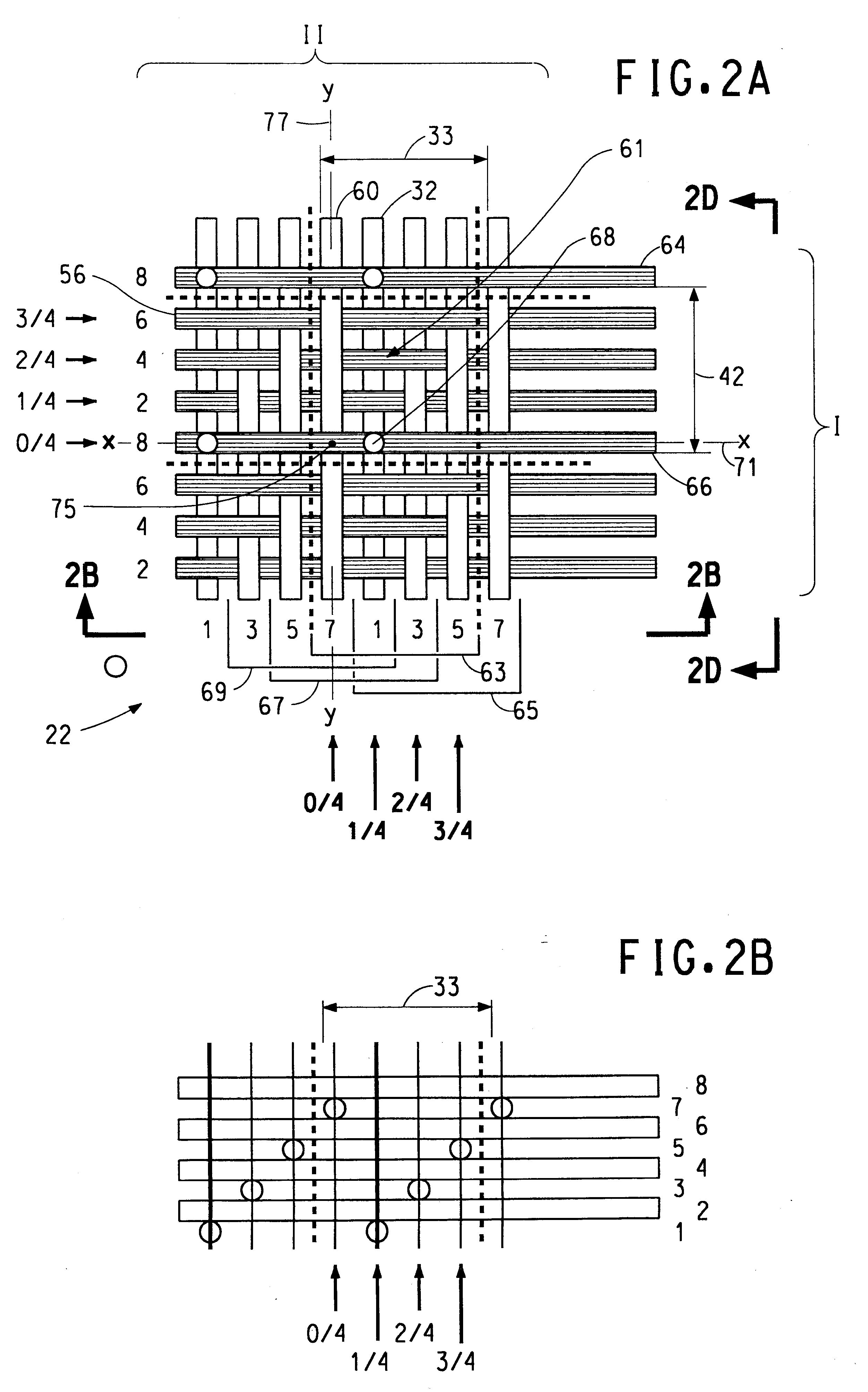
A flexible penetration resistance stabilized composite yarn structure was made to resist penetration. As proof of performance, it was tested in a ballistics application. It was made by incorporating polymeric webs of thermoplastic resin in the yarn structure during fabrication to thereby have the resin act as a distributed binder to hold the yarn fibers together. The webs were in the form of a film. By varying the film thickness and / or the number of sheets, the amount of resin in the structure can be varied. In this example, the resin was 16% of the structure by weight. A sample was made using 850 denier aramid yarn sold under the trademark Kevlar.RTM. KM2 by E. I. du Pont de Nemours and Company of Wilmington, Del. 19880. It is a continuous multifilament yarn comprising 560 filaments with 1.52 denier / filament, and has a breaking tenacity of 26.4 grams / denier, a modulus of 570 grams / denier, an energy to break of 43.9 joules / gram, and an elongation to break of 3.9%.

The structure was m...

example 3

A flexible fabric structure was made similar to Example 2, samples 1-1 to 1-7 except the binder material was a polyethylene film 0.5 mils thick and the resin component of the structure was reduced from 16% to 10% by weight. This structure was designated B6B6B. The fabric was stabilized as in Example 2, so it can be handled without damage to the fabric structure. Unlike Example 2, this stabilized fabric was not further consolidated.

A ballistics composite for testing is constructed by taking the large sheet and cutting out 12 inch square pieces of stabilized fabric and stacking 14 pieces together and attaching them at the edges by sewing or application of tape folded over as in Example 2. The test samples are flexible, but are somewhat stiff (have a low drape). The results of testing the 14 layer ballistic test sample as in Example 2 is summarized below.

This composite article with less resin and more aramid yarn than the Example 2 test samples performed acceptably.

example 4

A flexible composite structure was made similar to Example 3 except the central sheet of film was omitted and the yarn was laid up in 12 subgroups of each group without interruption. The resultant composite layer had a resin content of 6% by weight of the composite structure.

A ballistics composite for testing is constructed by taking the large sheet and cutting out 12 inch square pieces of stabilized fabric and stacking 15 pieces together and attaching them at the edges by sewing or application of tape folded over as in Example 2. The test samples are flexible, but are somewhat stiff (have a low drape). The results of testing the 15 layer ballistic test sample as in Example 2 is summarized below.

This composite article with less resin and more aramid yarn than Examples 2 or 3 performed acceptably, even though the extra step of adding resin in the middle of the structure was omitted. The lower amount of resin was still sufficient to keep the yarns in place in the structure.


PUM

PropertyMeasurementUnit
angleaaaaaaaaaa
angleaaaaaaaaaa
angleaaaaaaaaaa

Abstract

This invention is directed to a flexible penetration resistant stabilized composite, that includes an interlaced yarn structure of yarns having a tenacity of at least 8 g / d, a tensile modulus of at least 150 g / d and an energy to break of at least 10 j / g. The yarn structure includes yarn subgroups alternately stacked together. There is also provided a polymeric web coextensive with, in contact with, and bound to the surface of one of the subgroups that at least partially contacts and is bound to the yarns in all the subgroups in the stack to thereby contain the subgroups in the stack in an interlaced yarn structure.

Description

The invention teaches a process and apparatus to rapidly form a flat or shaped fabric and the fabric formed thereby consisting of groups of yarn densely covering an area. Fabrics adapted to function as penetration resistant articles are taught.TECHNICAL BACKGROUNDTextile fabric to resist penetration is often formed from strands, or filaments, of high strength yarn that are tightly woven and arranged in a layer and then combined with other layers to form a penetration resistant panel. In some cases, each layer may be combined with a resin to bind the yarns together and distribute the penetration force between yarns in each layer. The resin would be a small percent by weight of the layer and the flexibility of the layer would be retained, so the panel would remain flexible. In other cases, the layer is combined with resin and then multiple layers are laminated together under pressure and elevated temperature so the layers are bonded to each other to form a monolithic structure that is...

Claims


Application Information

Patent Timeline
Patent Type & Authority Patents(United States)
IPC IPC(8): A41D31/00B32B5/08D04H3/04D04H3/07D04H13/00D04H3/14D04H3/02F41H5/04F41H5/00B63H9/06D04H3/05
CPCA41D31/0061D04H3/04D04H3/05D04H3/07D04H3/14D04H13/007F41H5/0485B32B5/08Y10T428/24132B63H9/0657Y10S428/902Y10S428/911Y10T428/24091Y10T428/24074Y10T428/24058A41D31/245Y10T442/674Y10T442/668Y10T442/671Y10T442/643B63H9/067B32B2307/54B32B27/32B32B27/12B32B5/024
Inventor POPPER, PETERTAM, ALBERT S.WALKER, WILLIAM CHARLESYNGVE, PAUL WESLEY
Owner EI DU PONT DE NEMOURS & CO
Why Eureka
Try Eureka