
Method and systems for a graphical real time flow task scheduler

a task scheduler and real-time flow technology, applied in the field of methods and systems for a graphical task scheduler for a manufacturing plant, can solve the problems of substantial time and energy lost in interfacing the process engineer with the computer programmers, the complexity of the conventional modeling system, and the inability of programmers to possess the knowledge of the plan

Inactive Publication Date: 2001-11-27
SCHNEIDER ELECTRIC SOFTWARE LLC
View PDF4 Cites 58 Cited by
  • Summary
  • Abstract
  • Description
  • Claims
  • Application Information

AI Technical Summary

Problems solved by technology

Conventional modeling systems are complex and require a user to program the plant model into a computer.
However, typically the process engineers associated with the design and optimization of a plant do not possess computer programming skills, while computer programmers do not possess the knowledge of the plant.
The amount of time and energy lost in interfacing the process engineer with the computer programmers is substantial.

Method used


Image

  • Method and systems for a graphical real time flow task scheduler
  • Method and systems for a graphical real time flow task scheduler
  • Method and systems for a graphical real time flow task scheduler

Examples


Embodiment Construction

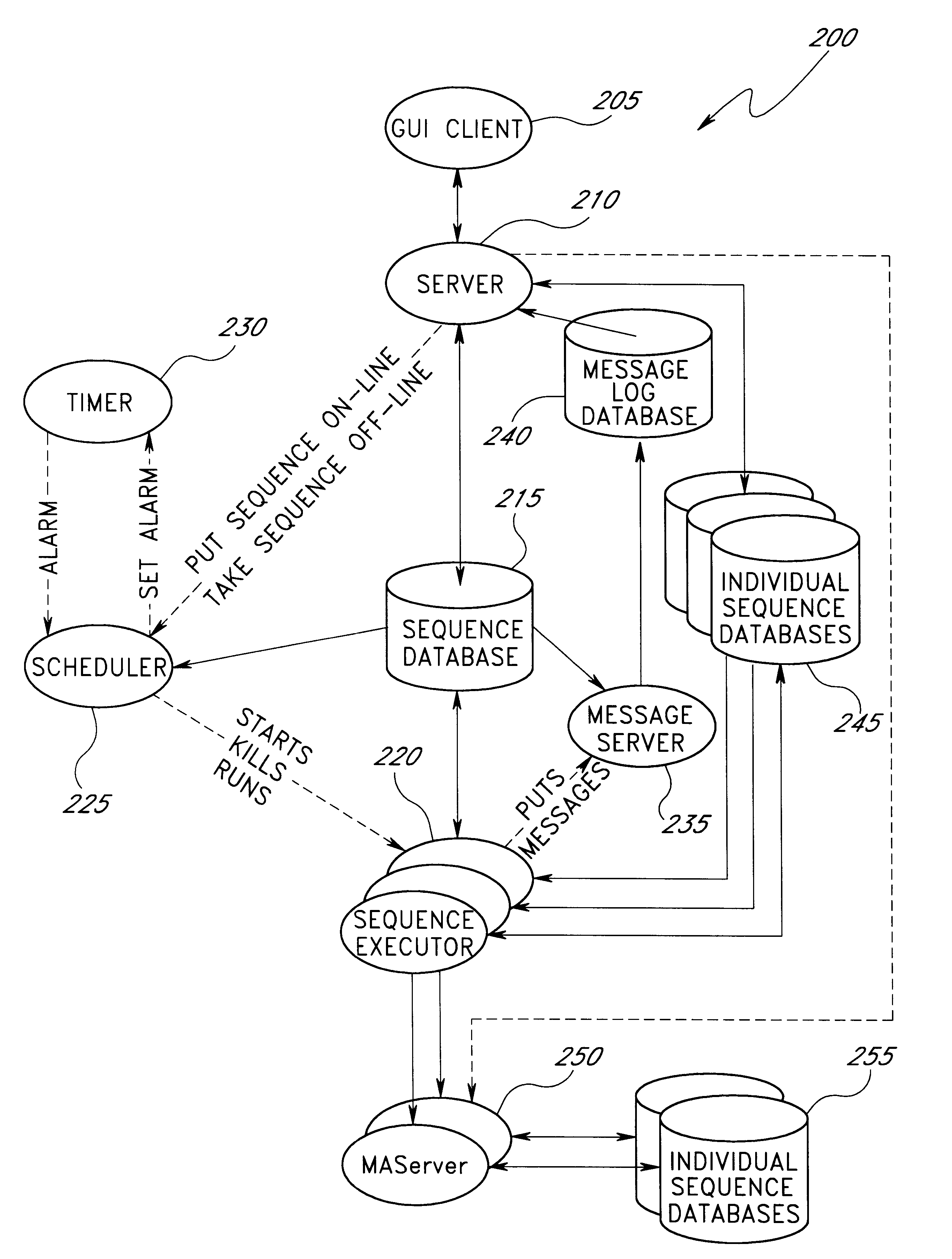
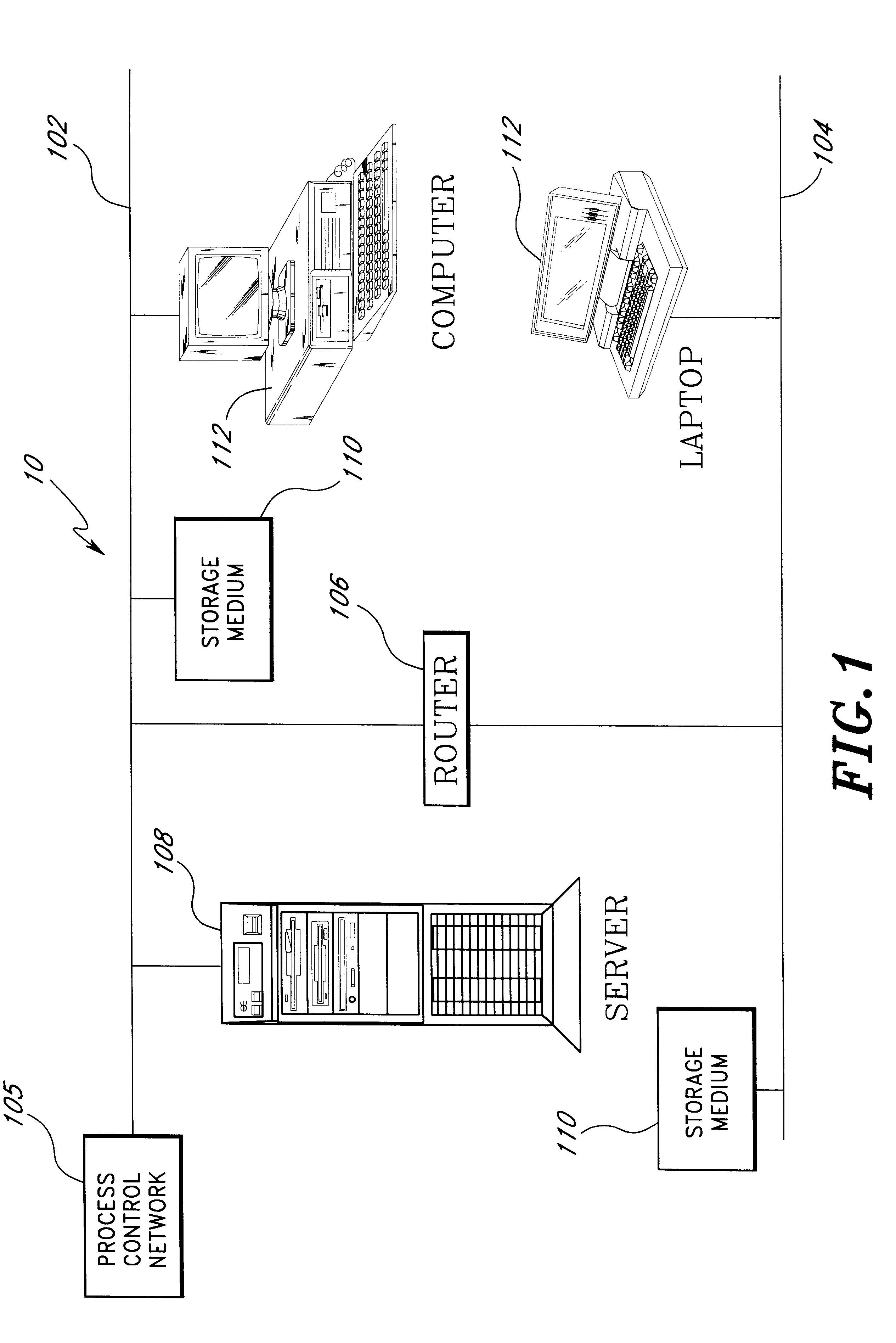
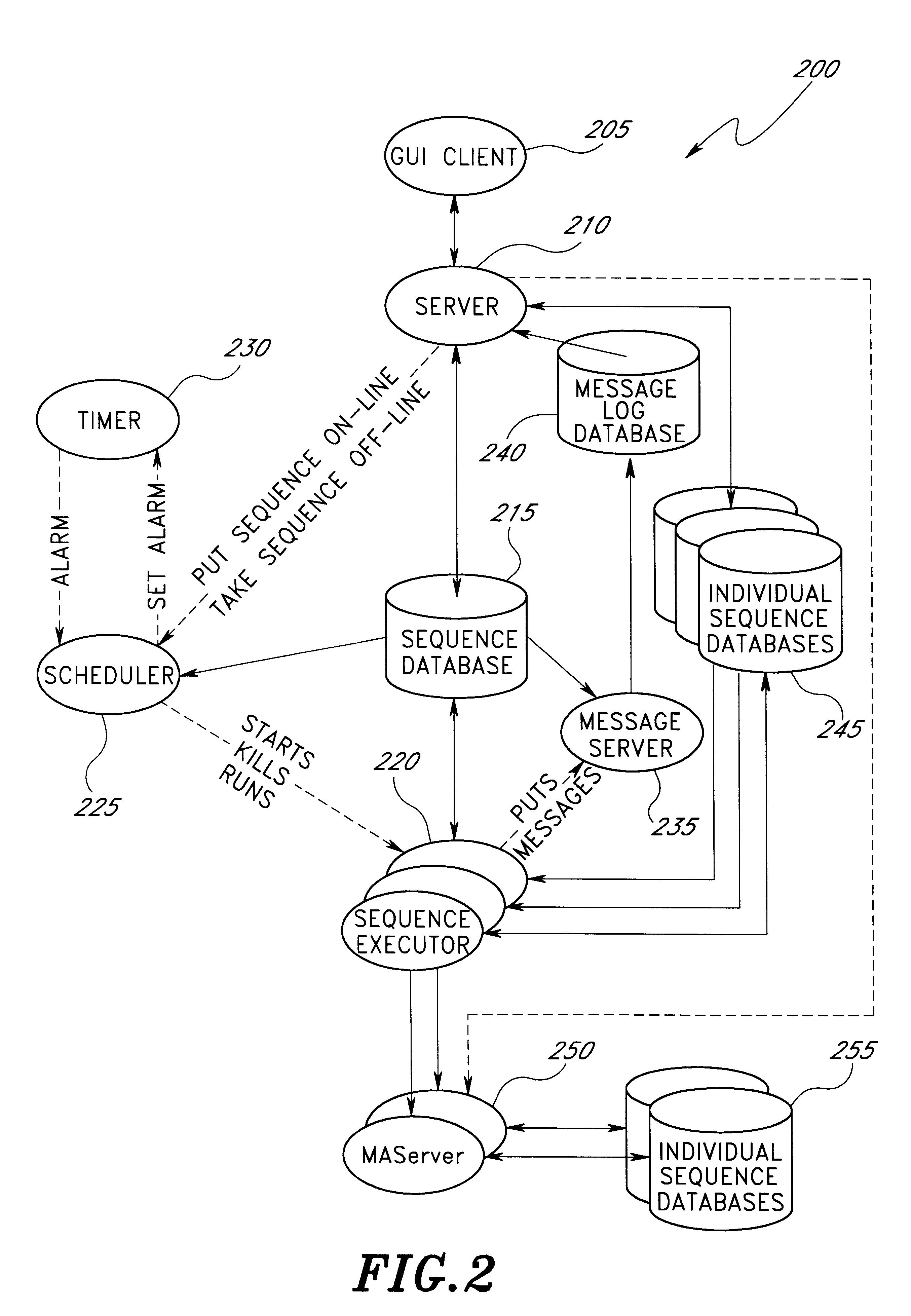
The network architecture for one embodiment of the present invention is indicated generally at 10 in FIG. 1. (In FIG. 1 and throughout the drawings, components which correspond to components shown in previous figures are identified using the same reference numbers.) The system 10 may include a local area network (LAN) 102 which is connectable to other networks 104, including other LANs or portions of the Internet or an intranet, through a router 106 or similar mechanism. One example of such a LAN 102 may be a process control network 105 to which process control devices including process control computers are connected. Process control networks 105 are well known in the art and are used to automate industrial tasks. The network 104 may be a corporate computing network, including possible access to the Internet, to which other computers and computing devices physically removed from the plant floor are connected. In one embodiment, the LANs 102, 104 conform to Transmission Control Prot...


PUM


Abstract

A system and method of creating and using a graphical task scheduler. A Graphical User Interface (GUI) allows a user to graphically build a real time flow task scheduler by providing a "click & drag" functional palette which contains graphical flow chart elements. By creating this graphical flow chart, the user is able to associate a plant layout, or any subpart of the entire plant, to its associated mathematical model. With a graphical flow chart, the user can define one or more exit branches for each task. For tasks with more than one exit branch, the user can specify the conditions causing the sequence to use each branch. Once the flow chart is set up, it can be used as a sequence editor or scheduler. The sequence editor defines the sequence of tasks that will be performed by an on-line application, such as optimization, and also allows scheduling of the on-line application at specific times or periodic intervals. The scheduler controls the running of each sequence based on the scheduling information. Once a plant has been optimized by the graphical task scheduler, the optimized data may be used to control plant operations.

Description

1. Field of the InventionThe present invention is related to systems and methods for providing a real time task scheduler for material processing systems. Specifically, the present invention relates to methods and systems for a graphical task scheduler for a manufacturing plant.2. Description of the Related ArtProcess industries, including but not limited to refining, chemical, petrochemical, and pharmaceutical processing, have experienced a need to operate ever more efficiently in order to remain competitive. This need has resulted in the development and deployment of process modeling systems. A process engineer uses these modeling systems to build a process model, or flowsheet, of an entire processing plant using equipment models provided by the modeling system. These flowsheet models are used to design and evaluate new processes, redesign and retrofit existing process plants, and optimize the operation of existing process plants. Typically, the process engineer must first build t...

Claims


Application Information

Patent Timeline
IPC IPC(8): G05B19/418G06Q10/00H04L29/08G06Q10/06
CPCG05B19/41865G06Q10/06H04L67/36H04L67/325H04L67/12H04L69/329G05B2219/32244Y10S715/965Y02P80/40Y02P90/02H04L67/62H04L67/75
Inventor JEROME, DAVID H.LINN, RICHARD EUGENE
Owner SCHNEIDER ELECTRIC SOFTWARE LLC
Learn More