
Evolutionary controlling system

a control system and evolution technology, applied in the direction of electric control, genetic algorithms, instruments, etc., can solve the problems of troublesome user checking the characteristics of the product, user may not like other operational characteristics, and cannot satisfy all of the users of the produ

Inactive Publication Date: 2001-11-27
YAMAHA MOTOR CO LTD
View PDF11 Cites 41 Cited by
  • Summary
  • Abstract
  • Description
  • Claims
  • Application Information

AI Technical Summary

Problems solved by technology

Thus, there is a problem in that even if imaginary users are selected to develop and design a product for users by presuming the users' preference, it is impossible to satisfy all of the users of the product.
However, it is troublesome for the user to check the characteristics of the product before purchase.
Further, because a series of products are often operated or controlled by characteristics common in the products, although the design of the product is changed depending on the user's preferences, the user may not like other operational characteristics.
Thus, although the design is appealing to some prospective users, the users may not purchase the product since the operational characteristics do not appeal to them.
In other words, there is another problem in that the range of users is limited and depends on the operational characteristics.
(a) shows that torque is high at low and intermediate speeds, but torque and fuel efficiency are low at a high speed.

Method used


Image

  • Evolutionary controlling system
  • Evolutionary controlling system
  • Evolutionary controlling system

Examples


first embodiment

In a first embodiment, the subject to be controlled is an engine installed in vehicles or vessels. However, in the evolutionary control system of the present invention, no restriction is imposed on the type of machine to be controlled, and as with the engine, a robot used in machine tools, a motor used in electrically-driven vehicles, or the like can be controlled by adopting the evolutionary control system based on the same principle as in the engine.

FIG. 4 is a schematic view showing the relationship between an engine 1 and a control device 10 performing the above-described evolutionary control system.

As shown in FIG. 4, the control device 10 controls the engine in such a way that fuel efficiency and acceleration performance are compatible with each other, by controlling the injection time period of an injector 3, the ignition timing of a ignition plug 5, and the valving timing of an intake valve 7, based on information input into the control device, such as the engine speed (r.p....

second embodiment

the evolutionary control system of the present invention will be explained with reference to FIGS. 15-20.

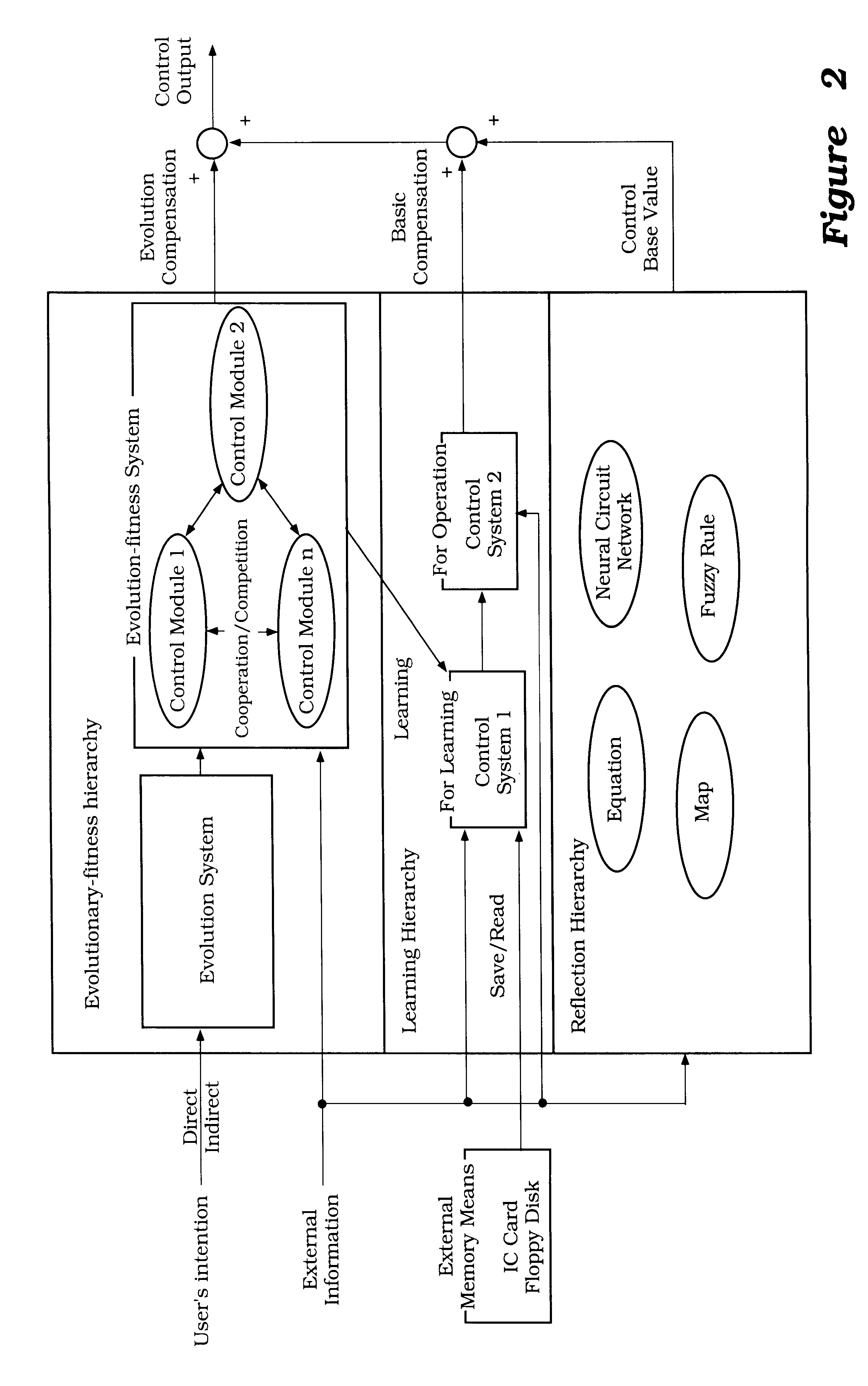
The difference between the previous first embodiment and the second embodiment resides in the manner of selection of control modules for evolution in the evolution-fitness layer for the evaluation system. In the first embodiment, selection is conducted based on the user's direct command or indication whereas, in the second embodiment, selection is conducted autonomously, based on a presumption of the user's intention. As with the first embodiment, the second embodiment will be explained in connection to an engine installed in vehicles or vessels. However, in the evolutionary control system of the present invention, no restriction is imposed on the type of machine to be controlled, and as with the engine, a robot used in machine tools, a motor used in electrically-driven vehicles, or the like can be controlled by adopting the evolutionary control system based on the same principle...


PUM


Abstract

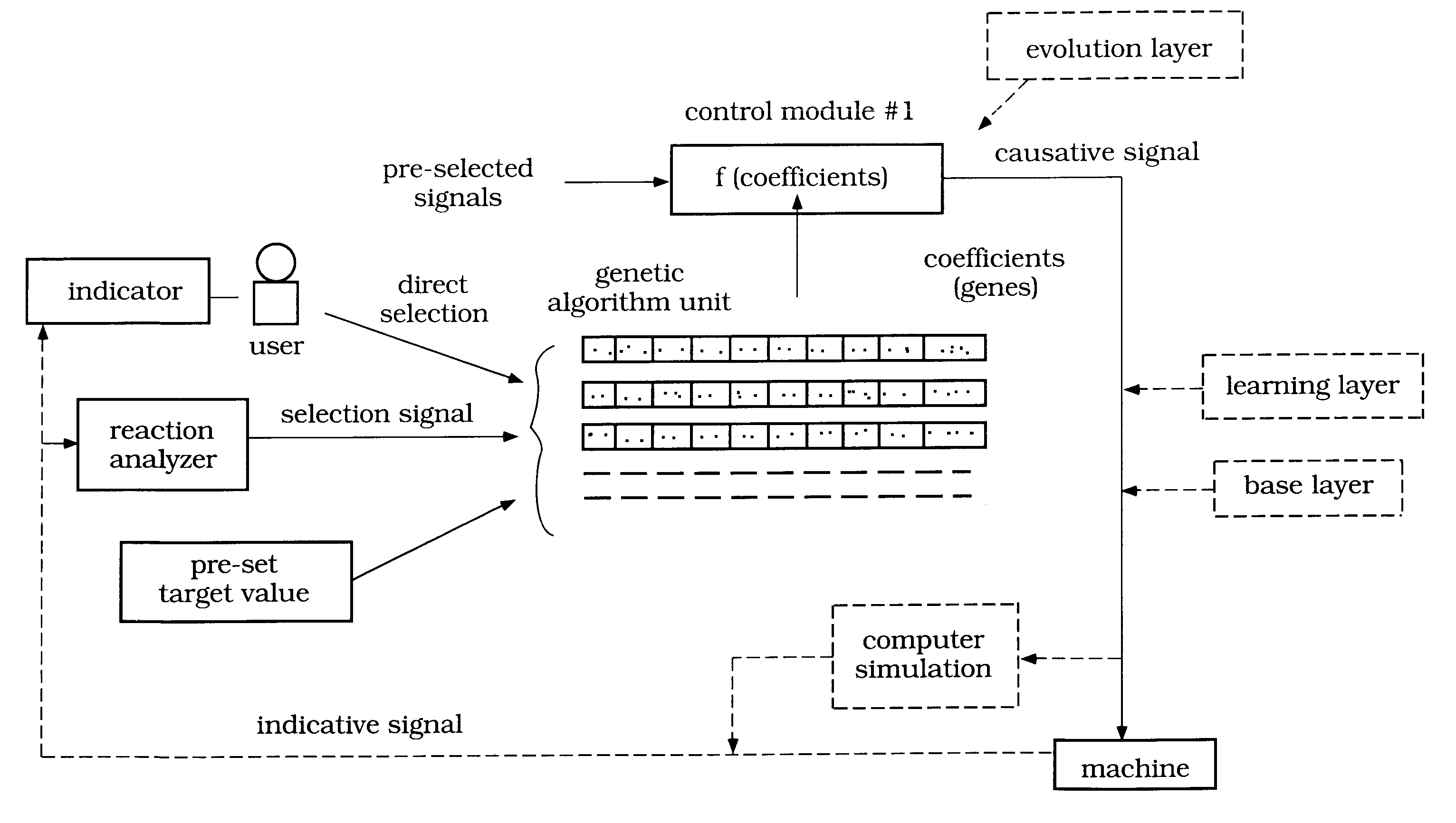
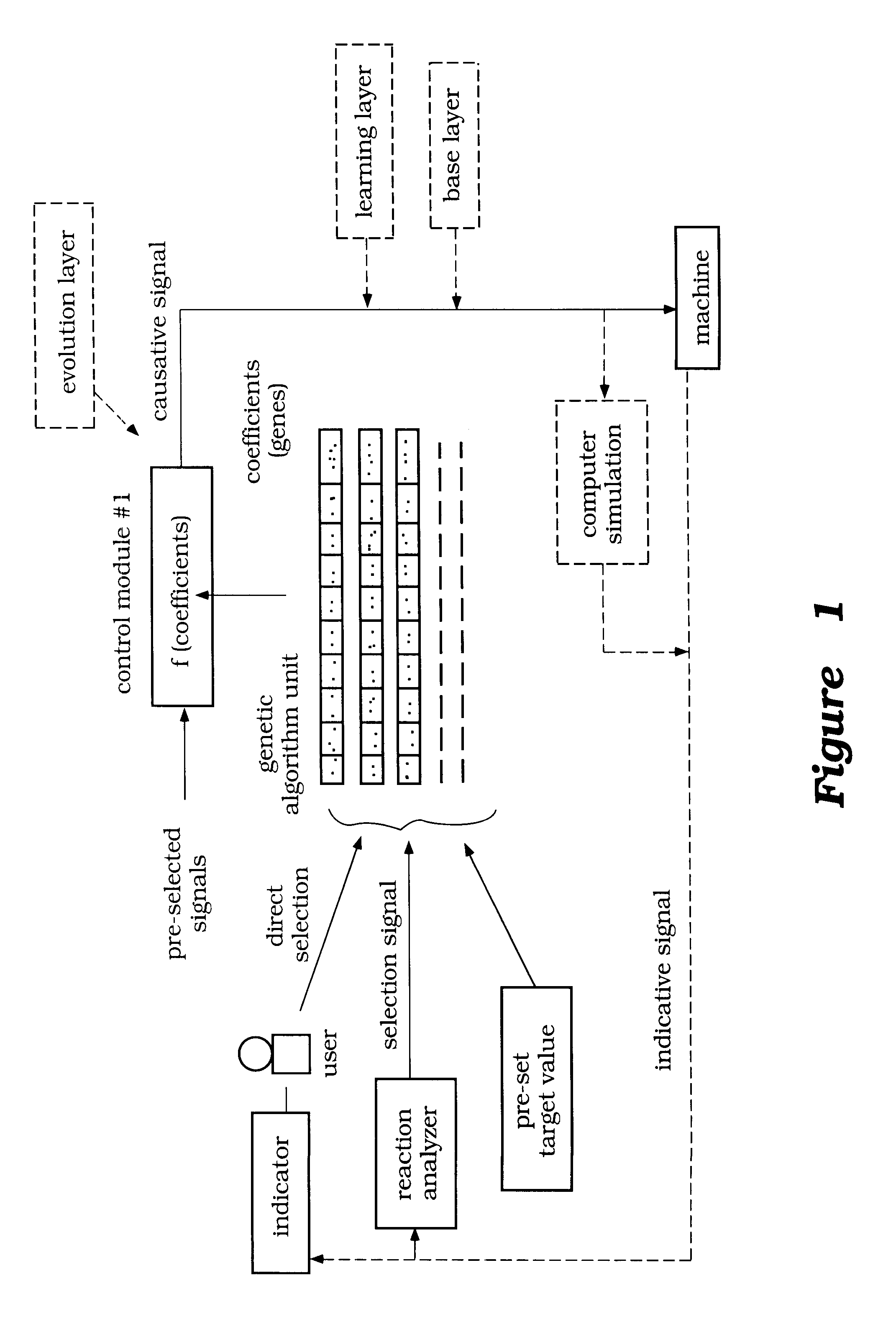
An evolutionary control for a subject such as an engine installed in a vehicle is conducted by the steps of: selecting coefficients, as genes, affecting the control characteristics of the control system; creating plural control units as chromosomes, each being constituted by plural genes; expressing the genes of each chromosome as control characteristics by controlling the subject using the control system having the control characteristics; selecting at least one chromosome from the created chromosomes based on the control characteristics expressed by the genes in view of the user's preference; and causing the at least one chromosome to evolve using a genetic algorithm, thereby obtaining control characteristics suitable to the user. In this method, the characteristics of the product can effectively be adjusted after its purchase based on the user's preference.

Description

1. Field of the InventionThis invention relates to an evolutionary controlling system, and particularly to that for controlling characteristics of a subject in an evolutionary manner.2. Description of Related ArtHeretofore, when a control system or control characteristics of a subject, such as vehicles and electrical appliances, is designed, imaginary users are selected, and the users' preferences and their using conditions are taken into consideration. The characteristics of the subject are determined in such a way as to adapt the subject to users in as broad a range as possible.However, each individual user has a particular and unique personality, and thus, their preferences are diverse. Thus, there is a problem in that even if imaginary users are selected to develop and design a product for users by presuming the users' preference, it is impossible to satisfy all of the users of the product.In order to solve the above problem, prior to purchase of a product, a prospective user is...

Claims


Application Information

Patent Timeline
IPC IPC(8): F02D41/14G05B13/02G06N3/12G06N3/00G06N3/08
CPCF02D41/1401G05B13/0265G05B13/027G06N3/086G06N3/126F02D41/1405
Inventor KAMIHIRA, ICHIKAIYAMAGUCHI, MASASHI
Owner YAMAHA MOTOR CO LTD
Learn More