Friction welding metal components

a technology of metal components and friction welding, which is applied in the direction of non-electric welding apparatus, aircraft floors, wings, etc., can solve the problems of limited design possibilities, manufacturing capabilities, and inherently complex design and subsequent manufacture of airframe structural components

Inactive Publication Date: 2001-12-11
AIRBUS OPERATIONS LTD
View PDF13 Cites 107 Cited by
  • Summary
  • Abstract
  • Description
  • Claims
  • Application Information

AI Technical Summary

Problems solved by technology

Airframe structural components are inherently complex in their design and subsequent manufacture owing to the large variety of stresses which will be applied to the structure in different phases of aircraft operation, eg static, level flight, climb, descent, take-off and landing or gust conditions.
However limitations upon designs which are achievable currently exist owing to restrictions on manufacturing capabilities, for example in terms of overall billet size combined with the unavailability of welded joints for many primary aircraft structures owing to the well-known fatigue-inducing and crack propagation qualities of welded joints.
An example of current design limitations in aircraft wing manufacture occurs in the available size of upper or lower wing skin panels for construction of a wing box.
The overall weight and cost of wing skins formed by the panels are increased.
The present limitation on panel size is caused by a limitation on size of the aluminium alloy billet from which the panel is rolled.
A further example of the limitations imposed by present technology occurs in the manufacture of solid alumini

Method used


Image

  • Friction welding metal components
  • Friction welding metal components
  • Friction welding metal components

Examples


Embodiment Construction

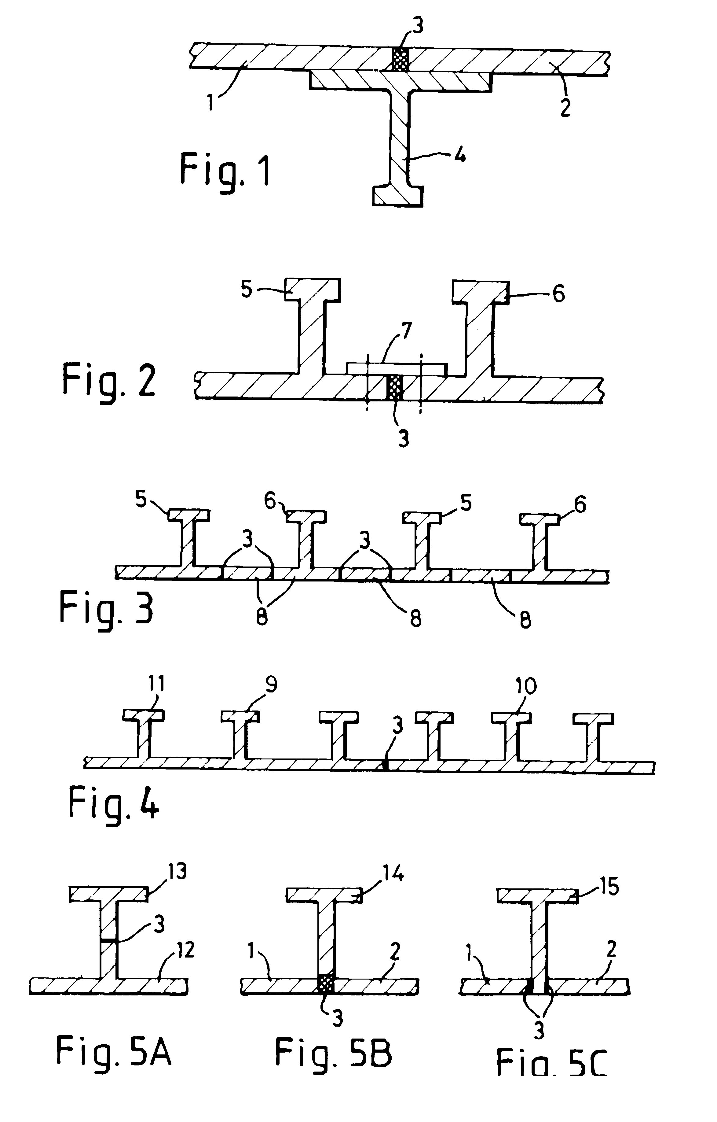
FIG. 1 shows skin panels 1, 2 friction stir butt welded together at 3 and having a stringer 4 bolted to the skin panels 1, 2 at either side of the weld 3. A secondary load path is thus provided and the need for a butt strap removed.

In FIGS. 2, 3 and 4 alternative structural assemblies for a wing skin or fuselage skin stiffened assembly are shown. Extruded panel stiffener members 5, 6 in FIG. 2 are shown friction stir butt welded together at 3 with a butt strap 7 bolted in position to members 5 and 6 either side of the weld 3. Again by this means it will be seen that a secondary load path is provided.

In FIG. 3, an arrangement similar to that of FIG. 2 includes intermediate skin portions 8 interposed between members 5 and 6 and friction stir butt welded in position with welds 3. Once again members 5,6 are extruded sections.

In FIG. 4, extruded sections 9, 10 are much wider and each include a number of stiffening portions 11 but are similarly friction stir butt welded at 3.

FIG. 5A, B an...


PUM

PropertyMeasurementUnit
Lengthaaaaaaaaaa
Thicknessaaaaaaaaaa
Electrical resistanceaaaaaaaaaa

Abstract

A method of forming a structural airframe component for an aircraft and an airframe structural component The method includes placing at least two components (1,2) in abutting relationship with each other and joining them together by friction stir butt welding (3), and the structural airframe component comprises a component manufactured according to the method of the invention.

Description

1. Field of the InventionThis invention relates to friction welding of metal, in particular aluminium alloy components, and in particular those used in situations where high strength is required such as in structures for aircraft, helicopters, hovercraft, spacecraft, boats and ships.2. Discussion of Prior ArtStructures and processes of the invention find particular application in aircraft structure, including primary structure, where strength to weight ratio is paramount.Airframe structural components are inherently complex in their design and subsequent manufacture owing to the large variety of stresses which will be applied to the structure in different phases of aircraft operation, eg static, level flight, climb, descent, take-off and landing or gust conditions. In order to simplify and reduce the number of airframe components it is a well known principle to integrally machine from solid billets such components. In this way the parts counts and therefore the weight, cost and comp...

Claims


Application Information

Patent Timeline
IPC IPC(8): B23K20/12B23K103/10B64C1/00
CPCB23K20/122B23K20/123B23K20/129
Inventor WOLLASTON, TIMPEDWELL, RICHARDBUSH, PAUL
Owner AIRBUS OPERATIONS LTD
Why Eureka
Try Eureka