
Air ride suspension system

a suspension system and air technology, applied in the direction of resilient suspensions, vehicle springs, vehicle components, etc., can solve the problems of poor stability, reduced torsion on leaf springs, and damage to air springs and shock absorbers. , to achieve the effect of slowing down the reaction time of air springs and improving stability

Inactive Publication Date: 2001-12-11
LIPPERT COMPONENTS MFG INC
View PDF26 Cites 22 Cited by
  • Summary
  • Abstract
  • Description
  • Claims
  • Application Information

AI Technical Summary

Benefits of technology

Yet another general object of the present invention is to provide a novel air ride suspension system for a vehicle which dissipates normal road vibrations and stress to provide a safe, smooth and longer lasting suspension, thereby resulting in an improved ride over prior act suspension systems, improved performance for recreational vehicle trailers, aluminum and steel gooseneck trailers, fifth wheel travel trailers, and improved life span of the vehicle.
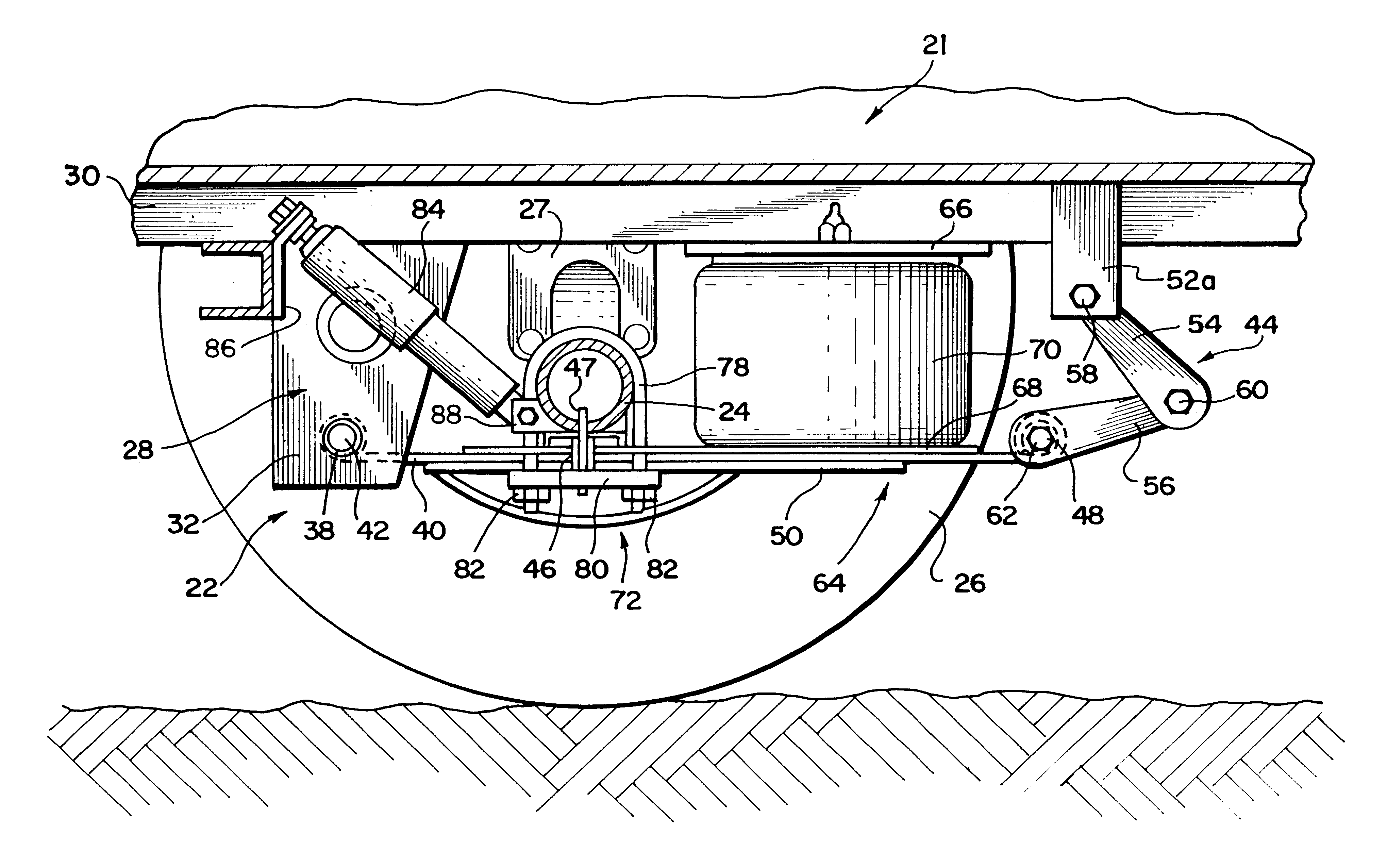
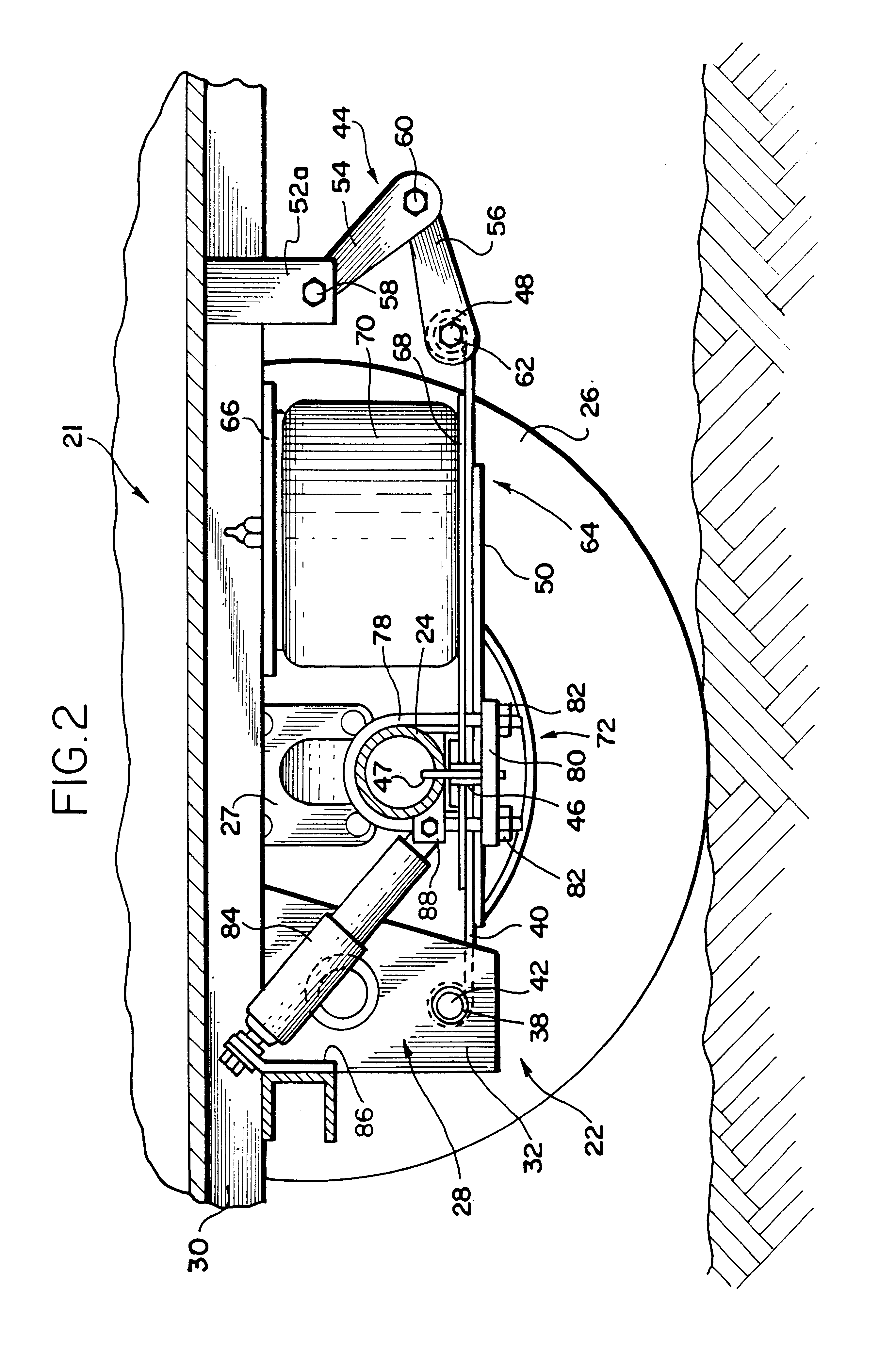
Another object of the present invention is to provide a novel air ride suspension system which uses a limiting assembly to secure a rear end of a spring member to a frame of the vehicle to prevent lateral movement of the spring member and subsequent lateral movement of the air spring and the shock absorber during use of the vehicle even during turning or backing up of the vehicle.
Yet a further object of the present invention is to provide a novel air ride suspension system which uses a limiting assembly to secure a rear end of a spring member to a frame of the vehicle to retain the spring member at a predetermined distance from the underside of the vehicle, thereby preventing the air spring from being torn apart during use which could happen if the distance the spring member travels exceeds the maximum allowable distance indicated by the air spring manufacturer.

Problems solved by technology

In addition, the design does not prevent lateral movement of the leaf spring and subsequent lateral movement of the air spring and the shock absorber during use of the vehicle even during turning or backing up of the vehicle which can cause damage to the air spring and the shock absorber.
Moreover, the design does not provide lateral stability through the extent of vertical travel of the leaf spring, which can result in poorer stability for and reduced torsion on the leaf spring, the air spring and the shock absorber.

Method used


Image

  • Air ride suspension system
  • Air ride suspension system
  • Air ride suspension system

Examples


Embodiment Construction

While the invention may be susceptible to embodiment in different forms, there is shown in the drawings, and herein will be described in detail, a specific embodiment with the understanding that the present disclosure is to be considered an exemplification of the principles of the invention, and is not intended to limit the invention to that as illustrated and described herein.

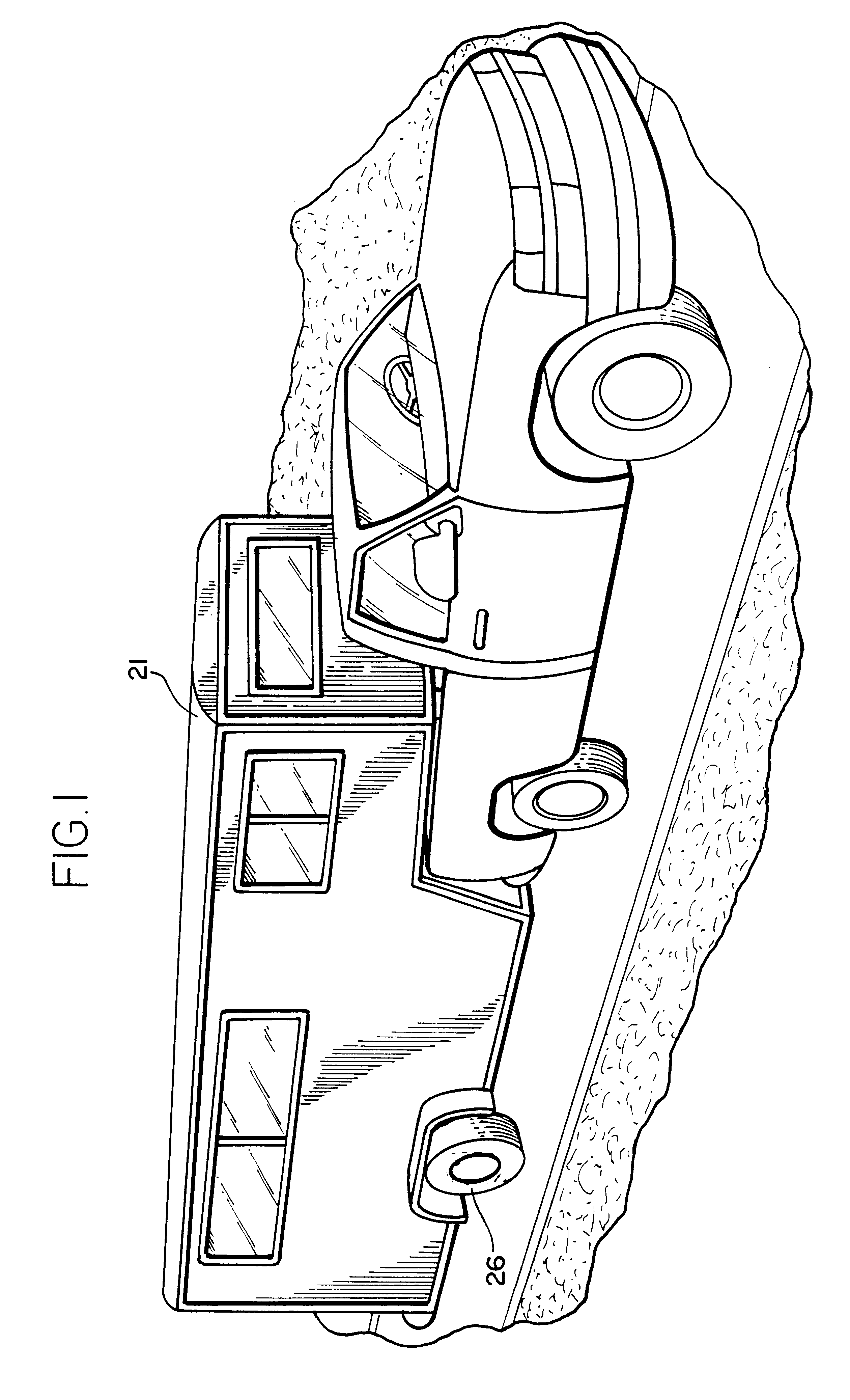
The present invention is an air ride suspension system 20 for a vehicle 21, particularly a trailer, which is primarily designed for axle capacities ranging in size from 3000 lbs. to 8000 lbs. These axles are primarily used in the gooseneck type horse trailer, race car (van) trailer, utility float trailers and all other kinds of recreational vehicle, gooseneck or fifth wheel travel trailer, and special use trailers under 26,000 lb. GVWR. The air ride suspension system 20 of the present invention dissipates normal road vibrations and stress to provide a safe, smooth and longer lasting suspension. This results in...


PUM


Abstract

The present invention provides a suspension system for a light duty trailer which includes a pair of modules. Each module is provided on an end of the axle and includes a spring member, a tower for connecting a front end of the spring member to an underside of the light duty trailer, an air spring connected between the underside of the light duty trailer and the spring member, and a limiting assembly for connecting a rear end of the spring member to the underside of the light duty trailer. In operation, if no bumps or ruts are encountered, the spring member remains generally horizontal relative to the underside of the light duty trailer. If a bump is encountered, the rear end of the spring member moves upwardly relative to the underside of the light duty trailer and the air spring compresses. If a rut is encountered, the rear end of the spring member moves downwardly relative to the underside of the light duty trailer and the air spring expands. The limiting assembly limits the amount of travel of the spring member.

Description

This invention is generally directed to a novel air ride suspension system for a vehicle, such as a trailer. More particularly, the invention contemplates a novel air ride suspension system for a vehicle which dissipates normal road vibrations and stress to provide a safe, smooth and longer lasting suspension, thereby resulting in an improved ride over prior art suspension systems, improved performance for aluminum and steel gooseneck trailers, recreational vehicle trailers, fifth wheel travel trailers, and improved life span of the vehicle.U.S. Pat. No. 5,362,095 to Eveley discloses a prior art air ride suspension system. In the '095 pattent, upper and lower leaf springs are pivotally connected at their front ends to a tower which is connected to an underside of the vehicle. An air spring is mounted between the underside of the vehicle and the rear end of the upper leaf spring. The axle is mounted to the upper and lower leaf springs. A shock absorber is provided between the tower a...

Claims


Application Information

Patent Timeline
Patent Type & Authority Patents(United States)
IPC IPC(8): B60G11/27B60G11/32B60G11/46B60G11/26B60G9/00
CPCB60G9/003B60G11/27B60G11/465B60G2200/30B60G2202/112B60G2202/152B60G2204/121B60G2204/128B60G2204/43B60G2204/45B60G2206/312
Inventor FENTON, E. DALE
Owner LIPPERT COMPONENTS MFG INC
Learn More