Polarization-insensitive laser stabilization using multiple waveguide gratings

a laser stabilization and waveguide technology, applied in the direction of laser optical resonator construction, laser details, optical resonator shape and construction, etc., can solve the problems of laser source dropout, system failure of laser source stabilization system, laser source reflected light not fully coherent in phase with laser source light, etc., to achieve efficient low-cost

Inactive Publication Date: 2001-12-11
JDS UNIPHASE CORP
View PDF14 Cites 12 Cited by
  • Summary
  • Abstract
  • Description
  • Claims
  • Application Information

AI Technical Summary

Benefits of technology

It is an object of the present invention to provide an efficient low-cost way to stabili...

Problems solved by technology

Another requirement for coherence collapse is that the reflected light must not be fully coherent in phase with the light emitted from the laser source.
Unfortunately, some systems that use reflectors to stabilize a laser source sometimes fail in the sense that the laser source drops out of coherence collapse and operates for an appreciable length of time in one of a number of longitudinal modes with occasional jumps between modes.
It has been determined that the cause of these failures is related to the polarization characteristics of the laser source and the optical waveguide.
Conversely, coherence collapse is much more difficult if not impossible to achieve if the reflected light is polarized...

Method used


Image

  • Polarization-insensitive laser stabilization using multiple waveguide gratings
  • Polarization-insensitive laser stabilization using multiple waveguide gratings
  • Polarization-insensitive laser stabilization using multiple waveguide gratings

Examples


first embodiment

2. First Embodiment of Two Reflectors

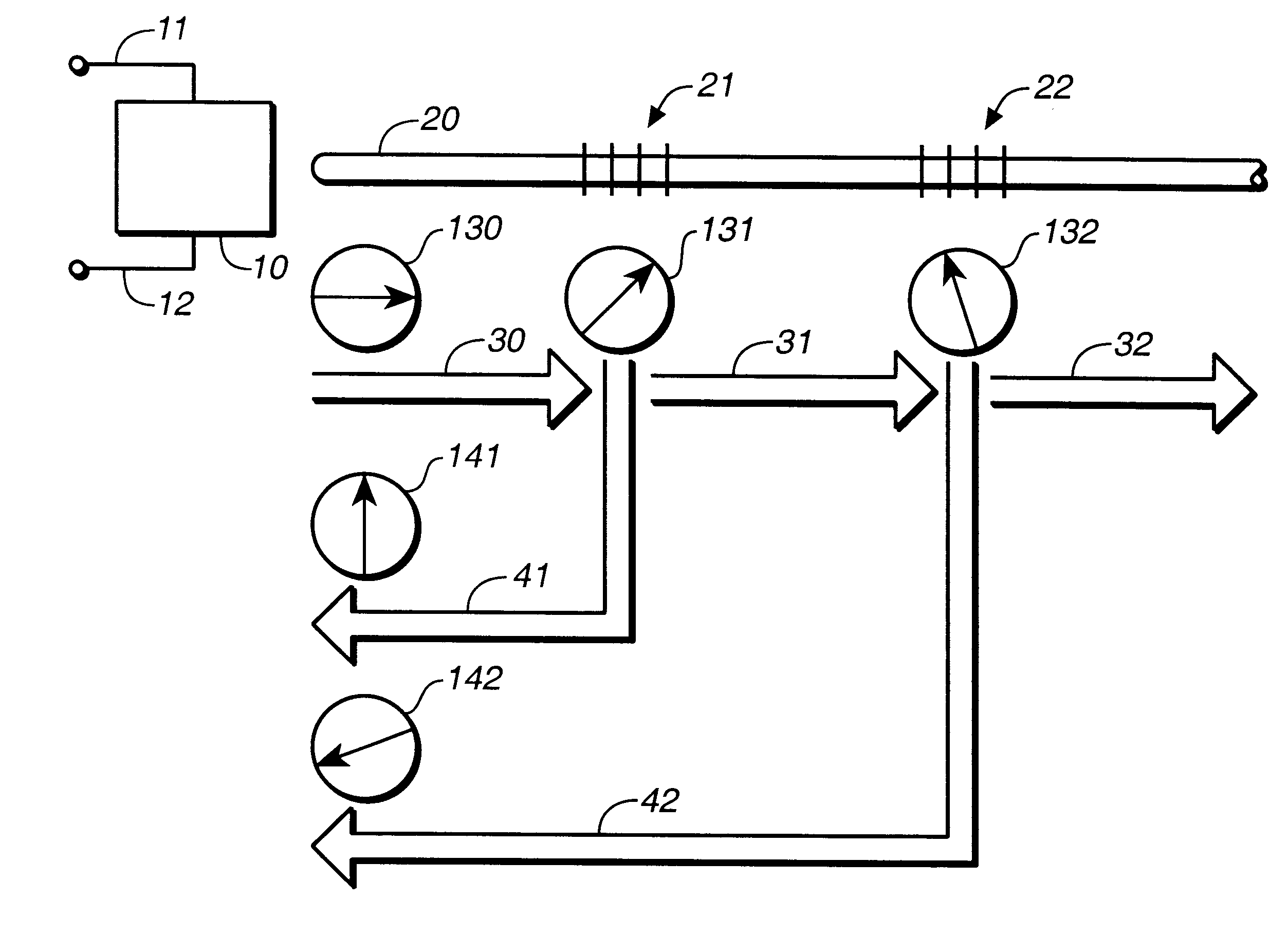
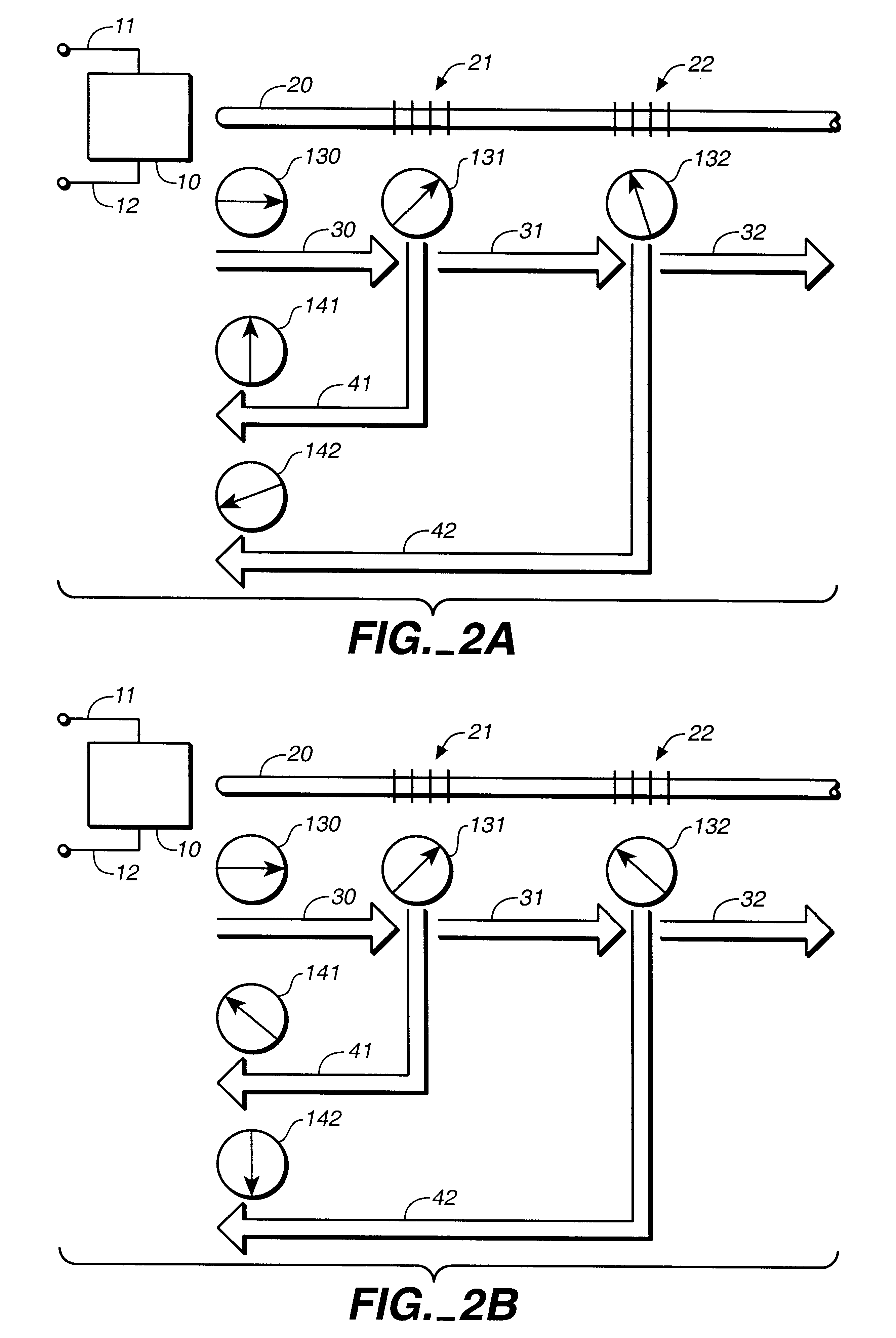
FIG. 2A is a schematic illustration of another embodiment of laser source 10 optically coupled to polarization-insensitive optical waveguide 20 in which reflector 21 is formed. These features, including the operating mode of laser source 10, the polarization orientation of emitted light 30 and the polarization orientation of reflected light 41, are identical to corresponding features in the embodiment illustrated in FIG. 1. In the embodiment illustrated in FIG. 2A, however, an additional reflector 22 is formed in optical waveguide 20. Symbol 132 represents the polarization orientation of light 31, which is not reflected by reflector 21, as it arrives at reflector 22.

A portion 42 of light 31 is reflected by reflector 22 toward laser source 10. The light 32 that is not reflected by reflector 22 continues along optical waveguide 20 away from laser source 10 and is available for use in an application. Because optical waveguide 20 is polarization inse...

second embodiment

3. Second Embodiment of Two Reflectors

FIG. 2B is a schematic illustration of yet another embodiment of laser source 10 optically coupled to polarization-insensitive optical waveguide 20, which comprises reflectors 21 and 22. The only difference between the embodiment of FIG. 2B and the embodiment of FIG. 2A is a difference in polarization orientations 131, 132, 141 and 142. A number of factors may cause a change in polarization orientation such as stress in optical waveguide 20, perhaps induced by coiling, changes in ambient temperature or changes in laser source drive current. Thus, the embodiments illustrated in FIGS. 2A and 2B can be considered representative of the same apparatus at two different instants of time.

In the embodiment illustrated in FIG. 2B, the polarization orientation 142 of reflected light 42 is substantially orthogonal to the polarization orientation 130 of emitted light 30; therefore, reflected light 42 is ineffective as a stabilizing influence on laser source ...


PUM


Abstract

The effectiveness of reflected light to stabilize the operational characteristics of a semiconductor diode laser varies with the polarization orientation of the reflected light. Stabilization failure can occur if the polarization orientation of the reflected light is orthogonal to the polarization of the light emitted by the laser source. The use of multiple reflectors can reduce the probability of stabilization failure by arranging the reflectors to return to the laser source portions of light having polarization orientations that are statistically independent with respect to each other.

Description

The present invention pertains generally to the use of optical waveguide reflectors to stabilize the operational characteristics of laser sources such as semiconductor diode lasers, and pertains more specifically to the use of multiple reflectors such as fiber Bragg gratings to improve the operational stability of laser sources when the laser sources are used with optical waveguides that do not maintain polarization.The operational characteristics of a laser source such as a semiconductor diode laser can be stabilized by reflecting a portion of the light emitted by the laser source back into the laser source's internal cavity. In applications where the emitted light of a laser source is coupled into an optical waveguide such as an optical fiber, these reflections can be obtained by forming reflectors in the optical waveguide. One common reflector is known as a fiber Bragg grating.The operational characteristics of the laser source are said to be stabilized in the sense that the wave...

Claims


Application Information

Patent Timeline
IPC IPC(8): H01S5/00H01S5/14
CPCH01S5/146H01S5/0656
Inventor MAJOR, JR., JO S.LUICK, GARNETBOOTH, IAN J.DAWSON, DAVID C.CHRISTO, FRITZWAARTS, ROBERT G.
Owner JDS UNIPHASE CORP
Why Eureka
Try Eureka