
Adjustable safety utility knife with easily removable blade holder

Inactive Publication Date: 2001-12-18
OLYMPIA IND
View PDF3 Cites 70 Cited by
  • Summary
  • Abstract
  • Description
  • Claims
  • Application Information

AI Technical Summary

Benefits of technology

It is another object of the present invention to provide an adjustable safety utility knife which is simple in construction and economical to manufacture.
It is still another object of the present invention to provide an adjustable safety utility knife which has in its handle a blade magazine for replacement blades which may be easily and safely removed.
It is yet another object of the invention to provide an adjustable safety utility knife which prevents cutting blades from inadvertently being dislodged from the handle housing when a replacement blade is sought to be extracted or removed.
It is a further object of the invention to provide an adjustable safety utility knife which ensures that the user need only handle a single blade during blade replacement.
It is still a further object of the present invention to provide an adjustable safety utility knife which includes a removable replacement blade magazine without altering the external ergonomic shape of the handle housing.
It is yet a further object of the present invention to provide an adjustable safety utility knife as in the previous objects which provides a ready access to individual blades within an internal blade cartridge without exposing the interior of the housing.

Problems solved by technology

These blades, therefore, are frequently replaced once they become dull.
However, these have the disadvantage that once the holder is removed from the handle, there is nothing to prevent one or more of the blades from falling out.
However, because these blades have their edges exposed, this can create a hazardous condition for the user when one or more blades with exposed edges may need to be handled.
Additionally, the provision of a relatively large finger opening exposes the interior of the handle cavity to exterior contaminants, including liquids, dust, etc., which may ultimately cause a deterioration of the internal operating components.
However, with the disclosed blade removal device, only a small portion of the blade becomes exposed through the upper slot which may render the blade difficult to grasp and remove.
Additionally, the angle at which the blade is positioned when in condition for removal such that it may contact other parts or components of the utility knife and, therefore, render removal more difficult or inconvenient.
However, when the handles are so pivoted, this also exposes the operative or active blade at the front end of the handle housing which can become dislodged and may need to be handled by the user.
Many of these use complex and costly constructions.
Additionally, the use of a rotary magazine requires a more complex construction, which significantly increases the cost of the unit.

Method used


Image

  • Adjustable safety utility knife with easily removable blade holder
  • Adjustable safety utility knife with easily removable blade holder
  • Adjustable safety utility knife with easily removable blade holder

Examples


Embodiment Construction

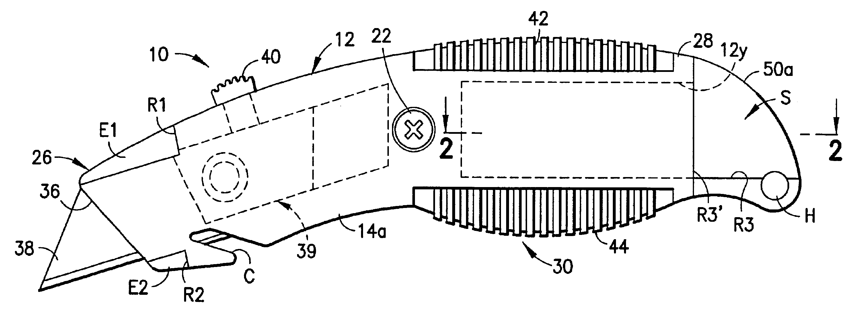
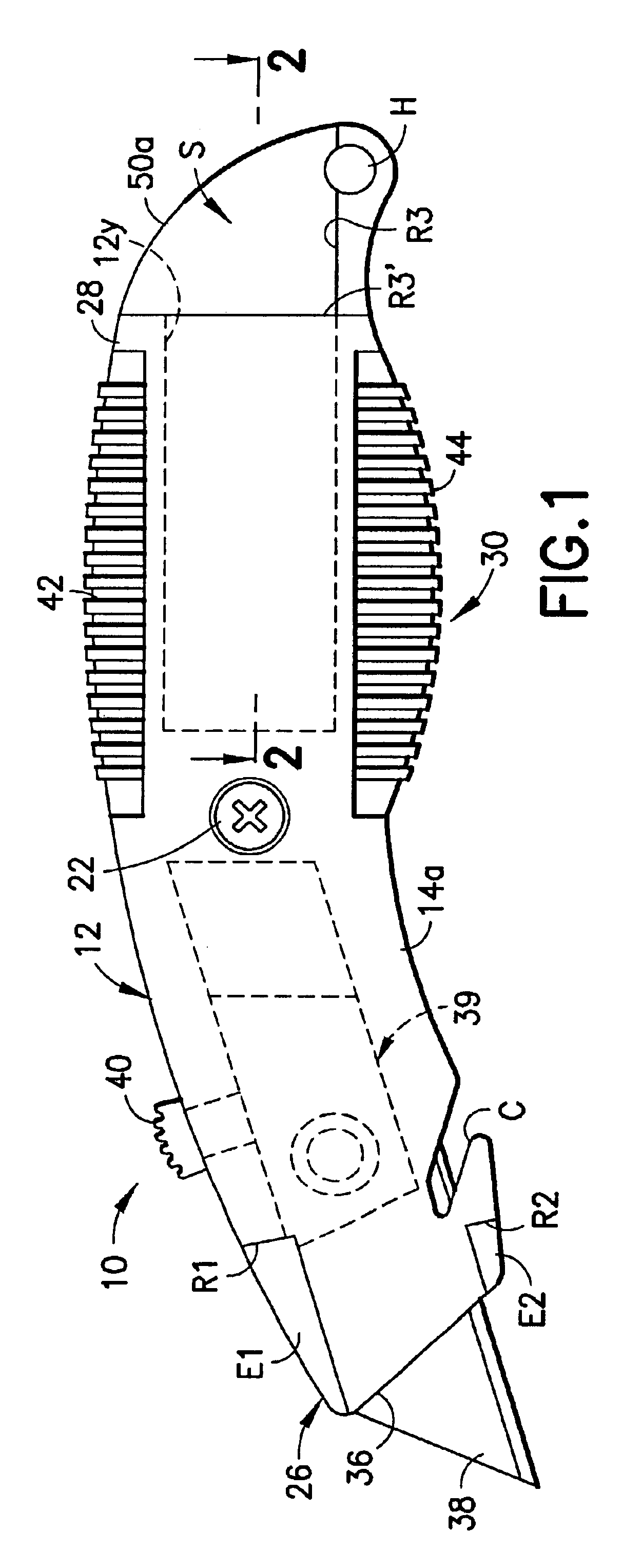
Referring now to the Figures, in which identical or similar parts are designated by the same reference numerals throughout, and first referring to FIG. 1, an adjustable safety utility knife in accordance with the present invention is generally designated by the reference numeral 10.

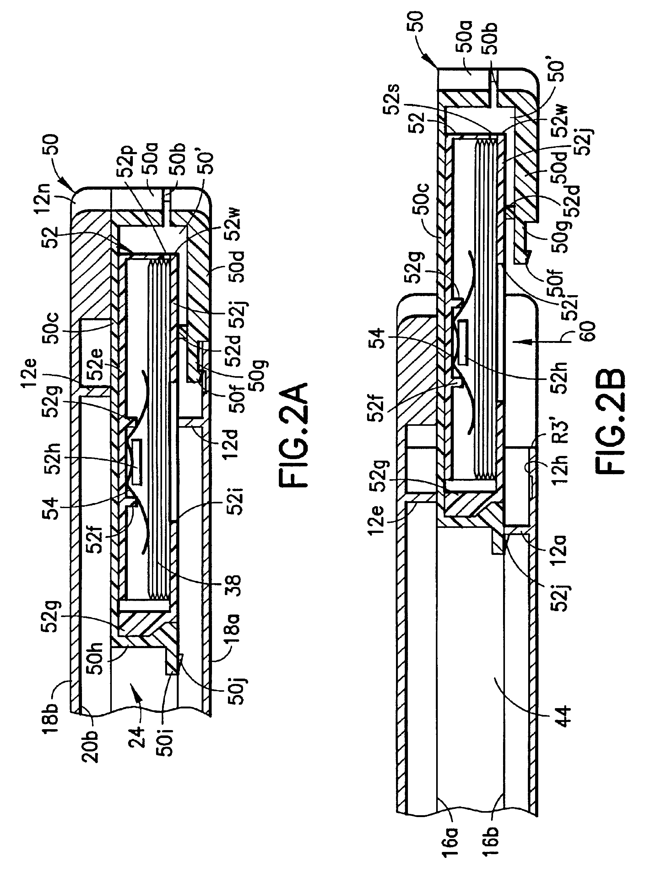
The utility knife 10 includes an elongated ergonomically shaped handle 12 formed of two elongate shell members 14a, 14b, each having a peripheral edge 16a, 16b, respectively, and outer generally convex surfaces 18a, 18b and inner generally concave surfaces 20a, 20b, respectively. A suitable fastener, such as a transverse screw 22 (FIG. 1) is provided for fastening the shell members 14a, 14b to each other at the peripheral edges 16a, 16b along a vertical parting plane P-(FIG. 2) to form an elongated internal cavity or compartment 24. The handle 12 defines a front end 26, a back end 28 and an intermediate portion 30 suitable to be gripped by the user, and also defines top and bottom surfaces 32, 34, respect...


PUM


Abstract

An adjustable safety utility knife includes an elongated ergonomically shaped handle formed of two elongate shell members each having a peripheral edge and an outer generally convex surface and an inner generally concave surface. The shell members are fastened at the peripheral edges along a vertical parting plane to form an elongated internal cavity. The handle defines a front end, a back end and an intermediate portion suitable for being gripped by a user and also defining top and bottom surfaces extending along opposite sides of the shell members along said peripheral edges. The handle has a slot-like aperture at the front end substantially aligned with the parting plane and dimensioned for passage of a flat cutting blade therethrough. A guide element within the elongated cavity guides the cutting blade between a first position for safely storing the blade fully inside said cavity and a second position for selectively extending the blade beyond the aperture to expose at least a portion thereof. A manually operated button arranged on the top surface is coupled to the guide element for selectively moving the blade between the first and second positions. The handle has a rear opening at the back end for providing access to the elongated internal cavity. A carrier frame has a blade cartridge receiving compartment and dimensioned to be removably receivable within the cavity through the rear opening between a retracted position in which the carrier frame is fully stored within the internal cavity of the handle end and an extended position in which the carrier frame is at least partially moved exteriorly of the back end to provide access of the cartridge receiving compartment. A blade cartridge for storing a plurality of flat cutting blades is receivable within the blade cartridge receiving compartment.

Description

1. Field of the InventionThe present invention generally relates to hand tools and, more specifically, to an adjustable safety utility knife with easily removable blade holder.2. Description of the Prior ArtUtility knives are widely used in construction, business and hobby applications for cutting such materials as paperboard, wallboard, string and other objects. Commonly, such utility knives are in the form of an elongate hollow housing that can be gripped by the user along an intermediate portion thereof and into which there are placed trapezoidal flat cutting blades. The blades typically have a single cutting edge. The blade is typically slidably mounted between a retracted position within the housing and an extended position in which the cutting edge is at least partially exposed through a front end aperture or slot, the slot being coupled to a manually operated element, such as a button positioned in a manner convenient to be actuated by the user's hand.Many utility knives incl...

Claims


Application Information

Patent Timeline
IPC IPC(8): B26B5/00
CPCB26B5/001
Inventor KHACHATOORIAN, ZAREHQIU, JIAN PING
Owner OLYMPIA IND
Learn More