Wood bending jig

a bending jig and bending technology, applied in the direction of work benches, manufacturing tools, clamps, etc., can solve the problems of consuming considerable time disassembly and the use of rounded structures, and achieve the effect of facilitating the construction of rounded stair cases

Inactive Publication Date: 2001-12-18
AUSTIN DONALD G
View PDF4 Cites 7 Cited by
  • Summary
  • Abstract
  • Description
  • Claims
  • Application Information

AI Technical Summary

Benefits of technology

It is an object of this invention to disclose a wood bending jig which facilitates the construction of rounded stair cases. A wood bending jig which can be used to fabricate both inner and outer stair stringers, stair railings, stair skirts, rounded beams for round openings through floors, as well as eliptical beams for openings through pitched roofs. It is an object of this invention to disclose a wood bending jig which eliminates the step of constructing a cylindrical form to build the rounded stair cases in and around. It is an object of this invention to disclose a wood bending jig which will allow stringers to be bent with and stair boards to be attached to the bent stringers directly and without the necessity of disassembling and then reassembling the stair case. It is yet a further object of this invention to disclose a wood bending jig which is adjustable to accommodate varying radiuses and pitches of inclination of varying stair cases. It is a final object of this invention to disclose a wood bending jig which can accommodate even complex curves, curves which have varying radiuses along their periphery.

Problems solved by technology

However, despite their inherent beauty, the labor intensive and time consuming task of constructing rounded structures severely limits their use.
Considerable time and materials are utilized fabricating the cylindrical wall form and considerable time is consumed disassembling, then reassembling the stringers and stair boards after the cylindrical wall form has been removed.

Method used


Image

  • Wood bending jig
  • Wood bending jig

Examples


Embodiment Construction

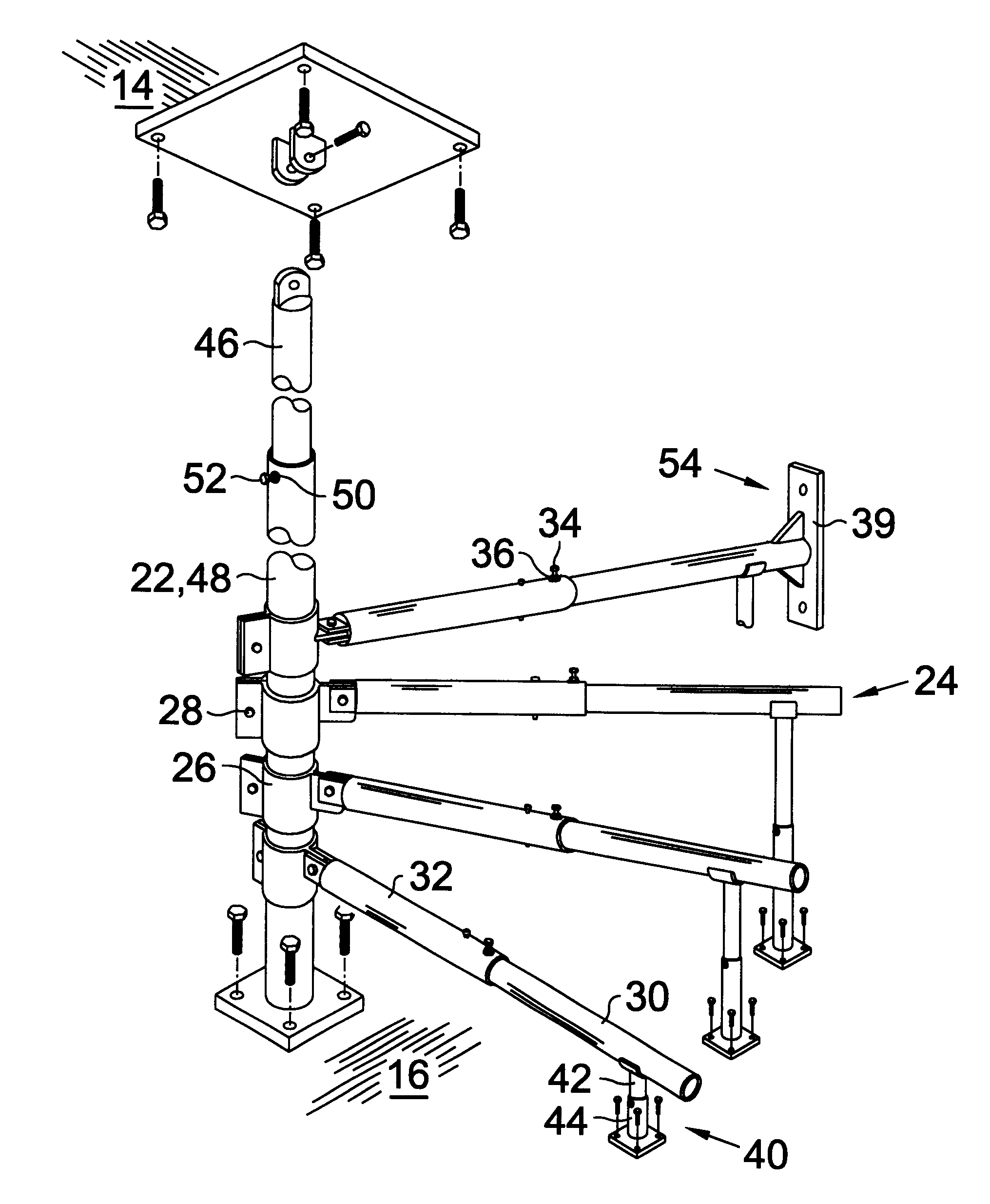
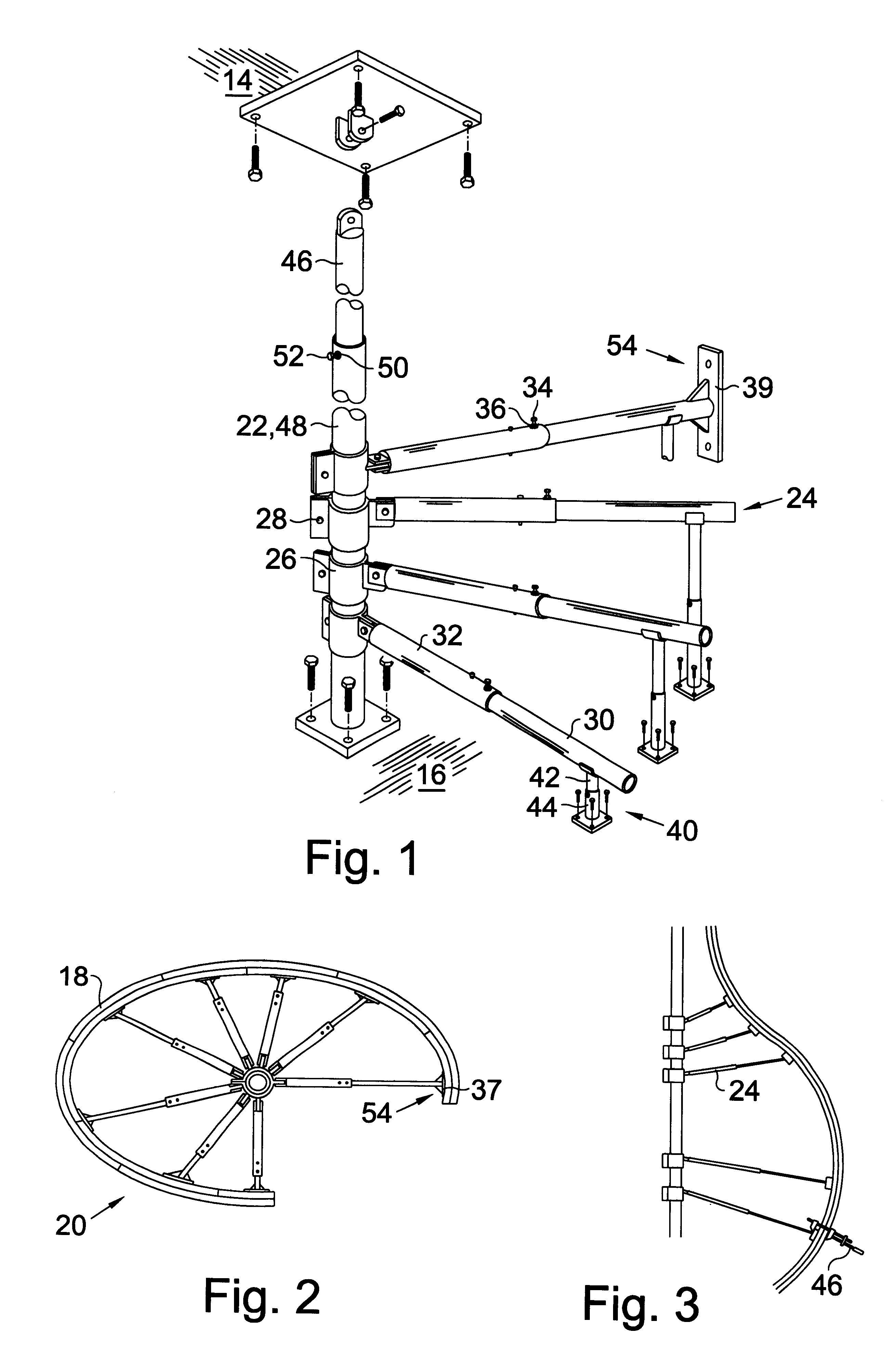
Turning now to the drawings and more particularly to FIG. 1 we have a partial perspective view of a wood bending jig 20. The jig 20 for bending a wooden board 18, above a supporting surface 16 comprises: a trunk 22; and, multiple arms 24 each arm 24 having an inner end portion releasably attached to the trunk 22 and an outer arm portion adapted to removably attach the wooden board 16 thereto. When the wooden board 18 is attached to the outer end portions of the arms 24 the wooden board 18 will have bent to conform to a curve defined by the end portions of the radial arms 24 as it extends up, and around the trunk 22.

Most preferably a bottom end portion of the trunk 22 is adapted to attach to the supporting surface 16 and a top portion of the trunk 22 is adapted to attach to a supporting member 14 so that the trunk 22 may be rigidly held in an upright position. Most preferably the trunk 22 and arms 24 comprise cylindrical tubes. In the most preferred embodiment of the invention the ar...


PUM


Abstract

A jig having particularly advantageous application in the construction of custom spiral staircases. The jig for bending a wooden board comprises: a trunk; and, multiple arms each arm having an inner end portion releasably attached to the trunk and an outer arm portion adapted to removably attach the wooden board thereto. When the wooden board is attached to the outer end portions of the arms the wooden board will have bent to conform to a curve defined by the end portions of the arms as it extends up, and around the trunk. Most preferably the trunk and arms comprise cylindrical tubes. The arm portions which attach to the trunk comprise split cylinders which may be lockably squeezed over the trunk with a bolt. Each arm comprises an inner cylindrical tube which closely and lockingly slides within an outer cylindrical tube so that the outer end portion of the arm may be locked at a selected radius from the trunk so that the jig may be used to bend boards at varying radiuses.

Description

This invention relates to the construction of curved wooden structures with bent wooden boards. More particularly this invention relates to a wood bending jig which can be adapted to bend boards on any selected radius and which can accommodate even complex curves. The jig has particularly advantageous application in the construction of custom spiral staircases.Arches and curves provide a beauty and eye appeal in architectural structures which is not provided by square lines. However, despite their inherent beauty, the labor intensive and time consuming task of constructing rounded structures severely limits their use. When a round staircase is built a large cylindrical wall form which will circumscribe the staircase is first fabricated. The stringers are then wrapped around this form, and the stair boards are fitted into the form with angles bolted to the wall form. Finally the wall form is removed from the stinger and stair boards; and the stair boards are fastened directly to the ...

Claims


Application Information

Patent Timeline
Patent Type & Authority Patents(United States)
IPC IPC(8): B25B5/00B27D1/00B27D1/08B27H1/00B27M3/12
CPCB25B5/003B27D1/083B27H1/00B27M3/12
Inventor AUSTIN, DONALD G.
Owner AUSTIN DONALD G
Why Eureka
Try Eureka