Eureka AIR delivers breakthrough ideas for toughest innovation challenges, trusted by R&D personnel around the world.

Dual nested plunger transfer molding system and method therefor

a technology of transfer molding and plunger, which is applied in the direction of large fixed members, applications, vices, etc., can solve the problems of increasing the pressure in the cavity during the epoxy curing stage, avoiding the use of hydraulics, and using compression springs

Inactive Publication Date: 2001-12-25
FITEL INNOVATIONS
View PDF17 Cites 2 Cited by
  • Summary
  • Abstract
  • Description
  • Claims
  • Application Information

AI Technical Summary

Benefits of technology

It is yet a further object of the invention to provide a transfer molding system that would not be subject to the mechanical stresses from gate-lock inherent in a transfer molding system having compression springs.

Problems solved by technology

However, more recently, the semiconductor industry has been turning away from the use of hydraulics because of the production of oil vapors from the hydraulic fluids and the associated contamination issues.
The transfer drive compresses the springs and pushes the plungers with a higher force, which results in an increased pressure in the cavities during the epoxy curing stage.
However, the use of compression springs also has some disadvantages.
This results in a sudden acceleration of the plunger which translates into a sudden increase in the epoxy injection flowrate.
Furthermore, successive areas of epoxy contamination will cause this unpredictable plunger movement to be repeated.
Additionally, as epoxy contamination is neither predictable nor controllable this renders the transfer molding process unpredictable and non-uniform.
(2) An additional disadvantage is that the displacement compensation results in a varied and unpredictable pressure at the start, during, and end of the curing phase thus resulting in varied and unpredictable curing process pressures both individually, and from cavity to cavity.
(3) Yet another disadvantage is that in the event of a gate-lock, the drive has to continue its movement and compresses the compression spring over a relatively large distance which results in a relatively great force on the drive and a high pressure in the present runner while a fault situation is present.
But again, this is a compromise because a low spring constant and a long length compression spring complicates the guiding and movement of the plunger and also results in a relative long transfer drive.

Method used


Image

  • Dual nested plunger transfer molding system and method therefor
  • Dual nested plunger transfer molding system and method therefor
  • Dual nested plunger transfer molding system and method therefor

Examples


Embodiment Construction

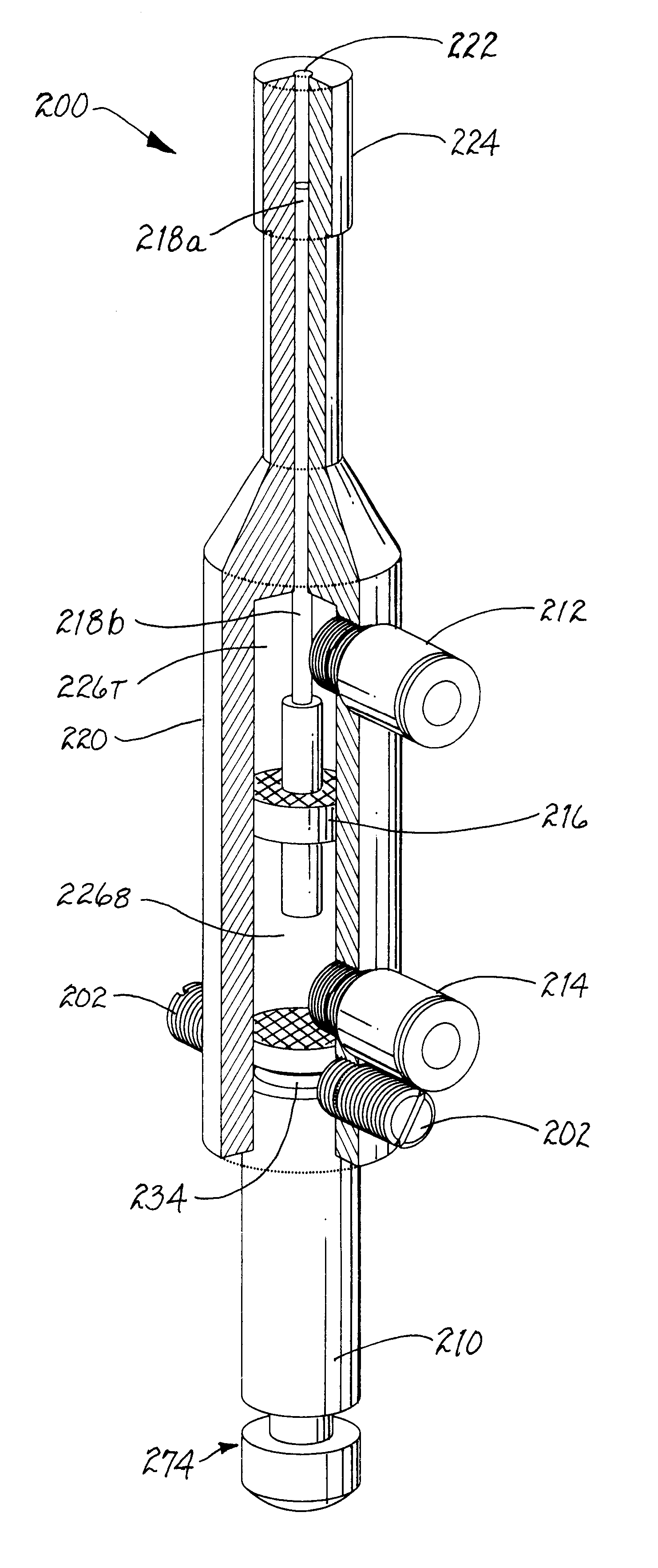
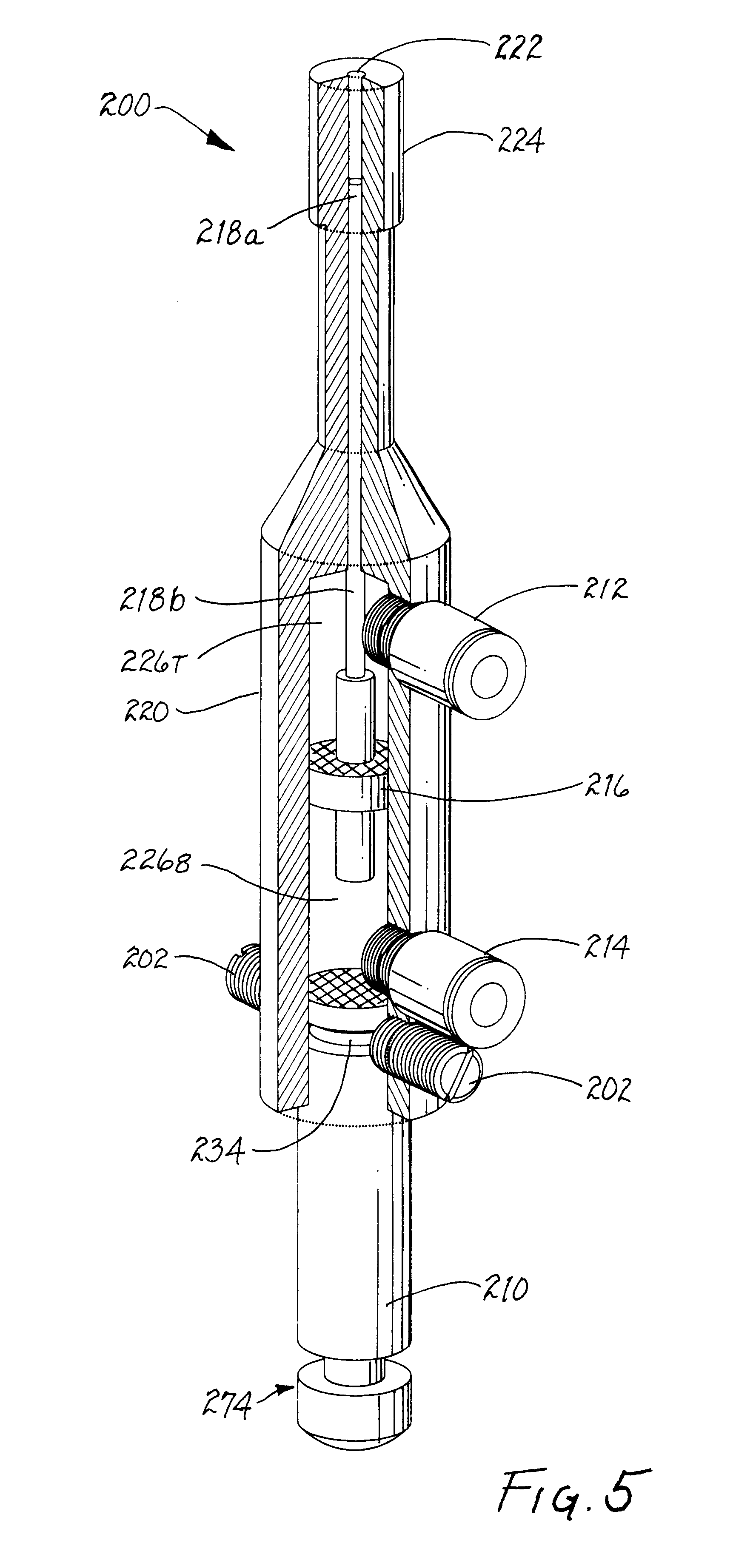
According to one aspect of the invention, a dual nested plunger transfer molding system is disclosed. The dual nested plunger transfer molding system, comprises: a transfer plunger having a piston chamber internally and co-axially positioned, integral within the transfer plunger; and a co-axial plunger slidably and co-axially coupled to the piston chamber. The co-axial plunger comprises: a co-axial plunger piston end, and a co-axial plunger drive end at the opposite end from the co-axial plunger piston end. The dual nested plunger transfer molding system further comprises a piston disc coupled to the co-axial plunger drive end, the piston disc cooperating with the piston chamber to form a slidable pressure boundary within the piston chamber.

According to another aspect of the invention, a transfer molding system having a plurality of dual nested plungers is disclosed. The transfer molding system comprises: a plurality of transfer plungers; a plurality of piston chambers internally an...


PUM

PropertyMeasurementUnit
pressureaaaaaaaaaa
densityaaaaaaaaaa
mechanicalaaaaaaaaaa

Abstract

A dual nested plunger transfer molding system. The dual nested plunger transfer molding system, comprises: a transfer plunger having a piston chamber internally, co-axially, positioned, integral within the transfer plunger; and a co-axial plunger slidably and co-axially coupled to the piston chamber. The co-axial plunger comprises: a co-axial plunger piston end, and a co-axial plunger drive end at the opposite end from the co-axial plunger piston end. The dual nested plunger transfer molding system further comprises a piston disc coupled to the co-axial plunger drive end, the piston disc cooperating with the piston chamber to form a slidable pressure boundary within the piston chamber.

Description

1. Field of the InventionThis invention relates generally to the transfer of epoxy, or other molding plastics or materials, into mold cavities for encapsulation of devices within the mold cavity, and more specifically, to semiconductor device encapsulating equipment wherein an epoxy transfer plunger has a second plunger placed inside the epoxy transfer plunger which serves both as an epoxy quantity compensatory and as an epoxy curing-pressure transmission device, and method therefor.2. Description of the Related ArtIn a transfer molding process, such as is used for semiconductor device packaging, a plunger transfers pelletized epoxy through a canal, or runner, through a cavity opening, or gate, and into a cavity. This transfer molding process may also utilize a plurality of cavities each having its own canals, gates, etc. After a cavity is filled with the epoxy which covers the semiconductor device located therein, usually mounted on a leadframe, the pressure applied to the liquid e...

Claims


Application Information

Patent Timeline
Patent Type & Authority Patents(United States)
IPC IPC(8): B29C45/77B29C45/58B29C37/00B29C45/02
CPCB29C45/586B29C45/77B29C37/005B29C45/02B29C2945/76498B29C2945/76545B29C2945/76765
Inventor TELKAMP, ARNOLD T. M.FIERKENS, RICHARD G. T.
Owner FITEL INNOVATIONS
Why Eureka
Eureka Blog
Learn More