Intake air duct

a technology of intake air duct and air intake, which is applied in the direction of combustion air/fuel air treatment, intake silencers for fuel, machines/engines, etc., can solve the problems of occupying the absorption apparatus, noise generated at the intake air duct, and irritating ears, so as to reduce the noise of the intake air. duct and reduce the cost

Inactive Publication Date: 2001-12-25
TOYODA GOSEI CO LTD
View PDF10 Cites 53 Cited by
  • Summary
  • Abstract
  • Description
  • Claims
  • Application Information

AI Technical Summary

Benefits of technology

The present invention has been developed in view of the aforementioned circumstances. It is an object of the present invention to provide an intake air duct, which reduces the intake air noises at low engine revolving speeds, which can take in ...

Problems solved by technology

In an intake air system of an automobile engine, there arises a problem in that noises are generated at an intake air duct when taking air in.
These intake air noises are irritating to ears particularly when the engines run at low revolving speeds.
Therefore, such a noise absorption apparatus occupies a large space in the engine room.
Accordingly, there may arise a drawback in that the degree of freedom decreases in boarding the other component members.
However, in the above-mentioned method in which the intake air passage is throttled, there may arise a problem in that...

Method used


Image

  • Intake air duct
  • Intake air duct
  • Intake air duct

Examples


example no.1

Example No. 1

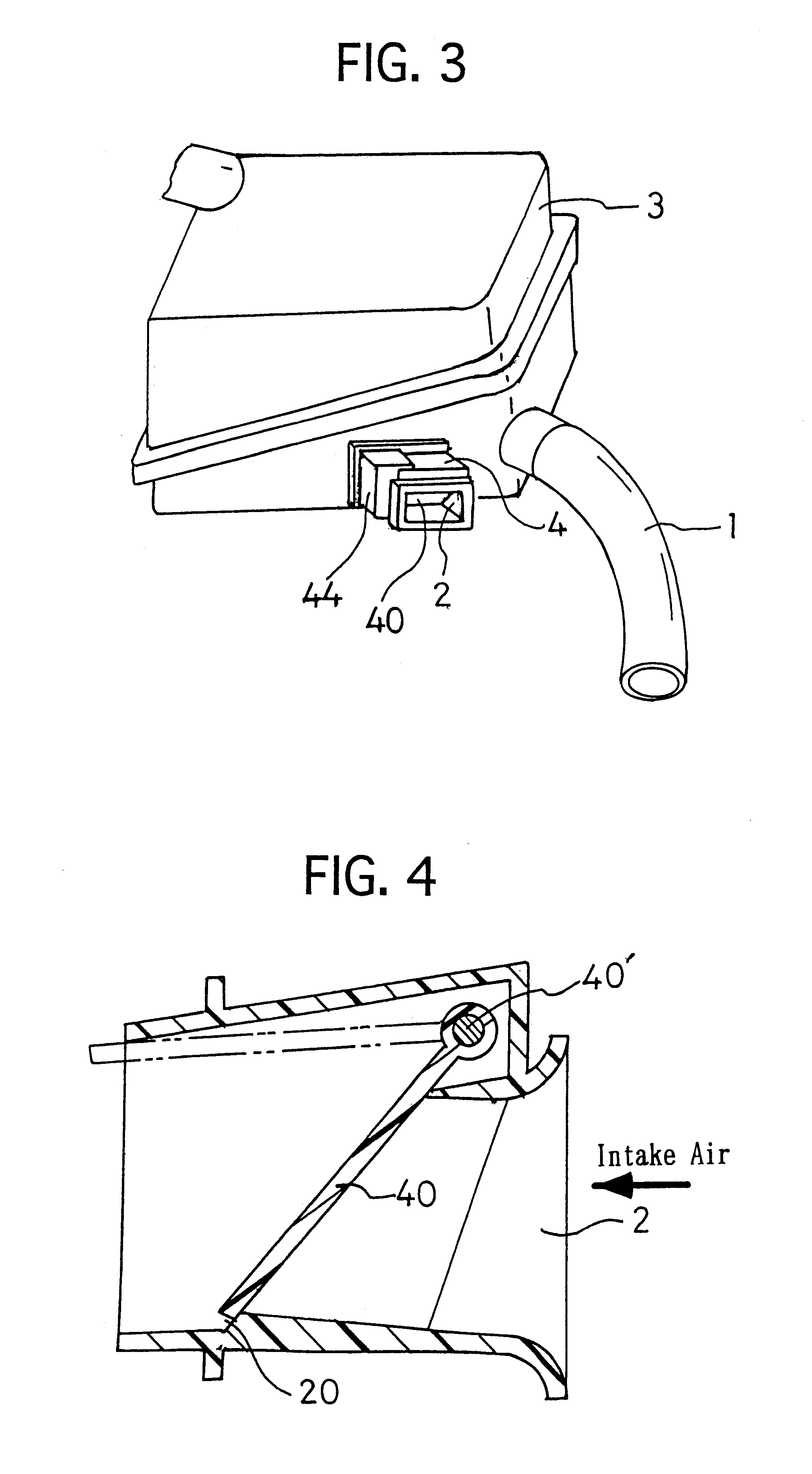
FIG. 3 illustrates Example No. 1 of an intake air duct according to the present invention. This intake air duct is connected to an air cleaner case 3 by a first intake air passage 1 having a minor diameter and a long length, and by a second intake air passage 2 having a larger diameter than that of the first intake air passage 1 and a short length.

The cross-sectional area of the first intake air passage 1 is arranged so that it is equal to the cross-sectional area of a .O slashed.40 mm pipe, and the cross-sectional area of the second intake air passage 2 is arranged so that it is equal to the cross-sectional area of a .O slashed.70 mm pipe. Moreover, a control unit 4 is formed adjacent to the inlet opening of the second intake air passage 2.

FIG. 4 illustrates the cross-sectional view of the control unit 4. As illustrated in the drawing, in the control unit 4, a valve 40 is held swingably by a supporting shaft 40'. Moreover, on an inner wall surface of the second intake ...

example no.2

Example No. 2

In FIG. 9, there is illustrated a major portion of this example of the present intake air duct. Except that the arrangement of the sliding member 50, which is disposed at the leading end of the coiled spring 5, is different from that of Example No. 1, and except that the construction of the valve 40 is different from that of Example No. 1, this intake air duct is arranged in the same manner as Example No. 1.

The sliding member 50 includes a rotatable rotor, and is fastened rotatably at the leading end of the coiled spring 5. Accordingly, in this intake air duct, the sliding member 50 rotates as the arm 41 moves. Hence, the coiled spring 5 can move remarkably smoothly.

Moreover, as illustrated in FIG. 10, the valve 40 is formed so that the joint between the supporting shaft 40' and the valve 40 has a heavy thickness. A cushioning member 42 is bonded on the outer rim of the valve 40. Accordingly, the strength of the valve 40 is improved. Moreover, when the valve 40 closes t...

example no.3

Example No. 3

Except that the shapes of the arm 41 and the sliding member 50 are different from those of Example No. 1, the, intake air duct of this example is arranged in the same manner as Example No. 1. As illustrated in FIG. 11, a guide groove 45 is formed in the arm 41. Moreover, the sliding member 50 includes a semi-eclipse-shaped head member 54 and a shaft member 55. The shaft member 55 is fitted into the leading end of the coiled spring 5. Thus, the head member 54 is arranged so that it is guided by the guide groove 45, and so that it is slid linearly.

Namely, the intake air duct of this example operates and effects advantages in the same manner as the above-described respective examples. The sliding member 50 is guided by the guide groove 45 so that it slides linearly therein. In addition, the coiled spring 5 is securely deformed in a predetermined direction only, because the wire end 53 of one of the opposite ends of the coiled spring 5 is fastened to the slit 25. Thus, it i...


PUM


Abstract

An intake air duct serves as a passage for supplying air to an engine, and includes a first intake air passage, a second intake air passage, an opening-and-closing valve, an interlocking member and a coiled spring. The opening-and-closing valve is disposed swingably in the second intake air passage so as to open and close the second intake air passage. The interlocking member is disposed outside the first intake air passage or the second intake air passage, and swings by interlocking with the swinging of the opening-and-closing valve. The coiled spring is disposed swingably outside the first intake air passage or the second intake air passage, and has a swinging end, which is brought into contact with a surface of the interlocking member. The swinging end slides on a surface of the interlocking member as the swinging of the interlocking member. The second intake air passage is opened by the opening-and-closing valve when a first urging force, which acts onto the coiled spring while the interlocking member swings so as to interlock with the opening-and-closing valve being swung in an opening direction by a negative pressure exerted in the second intake air passage, is larger than a second urging force, which is exerted by a spring elasticity of the coiled spring. The second intake air passage is closed when the first urging force is smaller than the second urging force.

Description

1. Field of the InventionThe present invention relates to an intake air duct, which serves as a passage for supplying air to an engine. More particularly, it relates to an intake air duct, in which noises are reduced when taking air in.2. Description of the Related ArtIn an intake air system of an automobile engine, there arises a problem in that noises are generated at an intake air duct when taking air in. These intake air noises are irritating to ears particularly when the engines run at low revolving speeds. Hence, a side branch and / or a resonator have been disposed in the air duct conventionally, and the noises of specific frequencies, which are calculated based on the Helmholtz resonance theory, have been reduced.However, a large branch extends as long as about 30 cm, and a resonator of a large volume enlarges as large as 14 liters. Therefore, such a noise absorption apparatus occupies a large space in the engine room. Accordingly, there may arise a drawback in that the degree...

Claims


Application Information

Patent Timeline
IPC IPC(8): F02M35/12F02M35/10
CPCF02M35/10013F02M35/10144F02M35/10262F02M35/10295F02M35/1222Y02T10/146Y02T10/12
Inventor KOMADA, MINORUFUJIHARA, KAZUOHIROSE, YOSHIKAZUKOMORI, TAKAHIROKINO, HITOSHIISHIHARA, HIDETOSHI
Owner TOYODA GOSEI CO LTD
Why Eureka
Try Eureka