

Boolean layer comparison slice
a layer comparison and slice technology, applied in the field of slicing of three-dimensional object representations, can solve the problems of affecting resolution, previous methods of forming layer representations suffered from a number, and methods typically do not make direct use of object representations generated from cad systems
- Summary
- Abstract
- Description
- Claims
- Application Information
AI Technical Summary
Problems solved by technology
Method used
Image

Examples
first embodiment
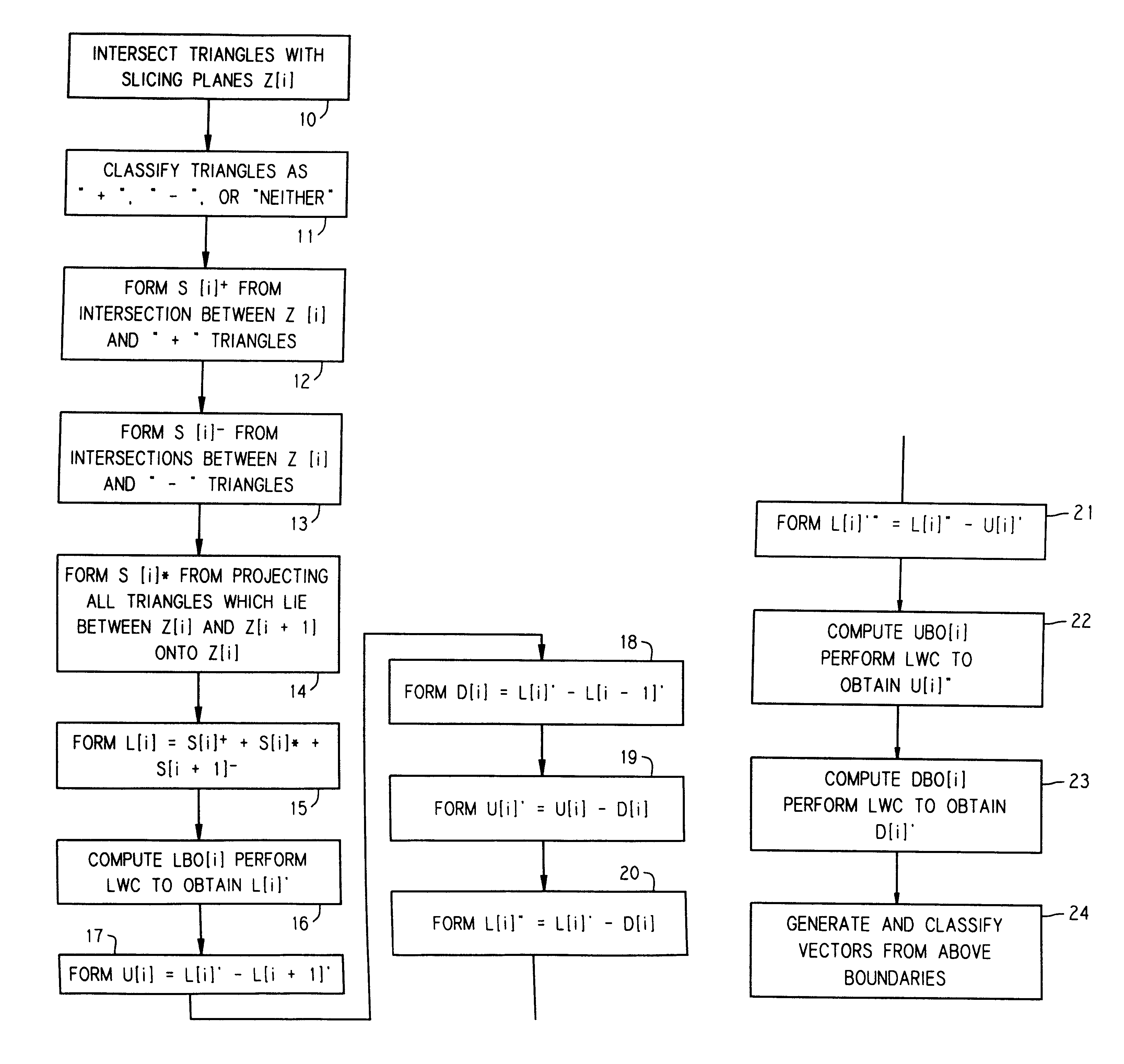
First, in step 50, all the triangles are sorted by the minimum z-component of any of the triangle vertices. The z-axis is assumed to be the slicing axis, which in the first embodiment, is the vertical dimension. Therefore, this step will order the triangles along the slicing axis. It should be noted that the choice of the z-axis is arbitrary, and, assuming a Cartesian coordinate system, the y or x-axis could equally have been used.
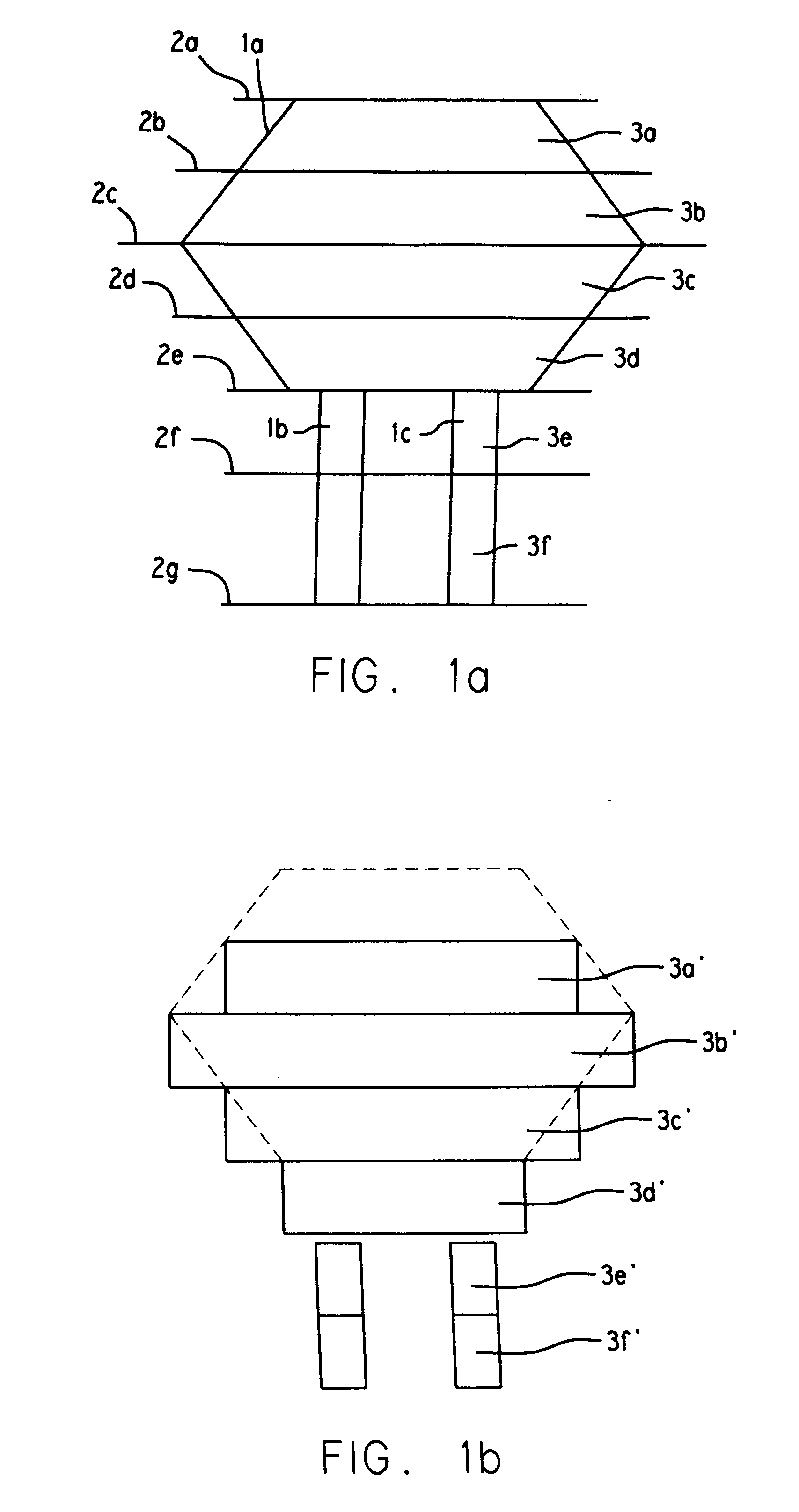
Then, in step 51, the triangles are overlayed with a plurality of slicing planes spaced along the z-axis. Then, after consideration of all the triangles between any two successive slicing planes, a segment list is generated, comprising segments generated from the intersections- of all such triangles with the one of the two successive slicing planes having the smaller z-component. In addition, a projection list is generated, comprising segments generated from the projections of triangles, between the two layers, onto the smaller z- component slicing plane, ...
second embodiment
This completes an overview of the major deviations. A flowchart of the second embodiment, provided in FIGS. 31a-d will now be discussed.
In this embodiment, functionality is provided in the form of computer software, executing on the SLICE computer. This program is also designed to be executable on the PROCESS computer as well. At present, the computer software is known as SCHLEISS, and comprises seven modules, known as S0.C to S6.C. A user's manual for SCHLEISS is provided in Appendix A, and a program listing is provided in Appendix B. The major functions performed by each module are listed in the header information contained at the beginning of the computer listing for that module, and are also provided at pp. 5-18, 20-29, and 81-118 of Appendix A. Module S0.C is the first module to be executed, and is the major module dictating the sequence in which all the remaining modules are invoked. The flowchart provided in FIGS. 31a-31d is keyed primarily to lines in the listing of S0.C.
Tur...
PUM
| Property | Measurement | Unit |
|---|---|---|
| thickness | aaaaa | aaaaa |
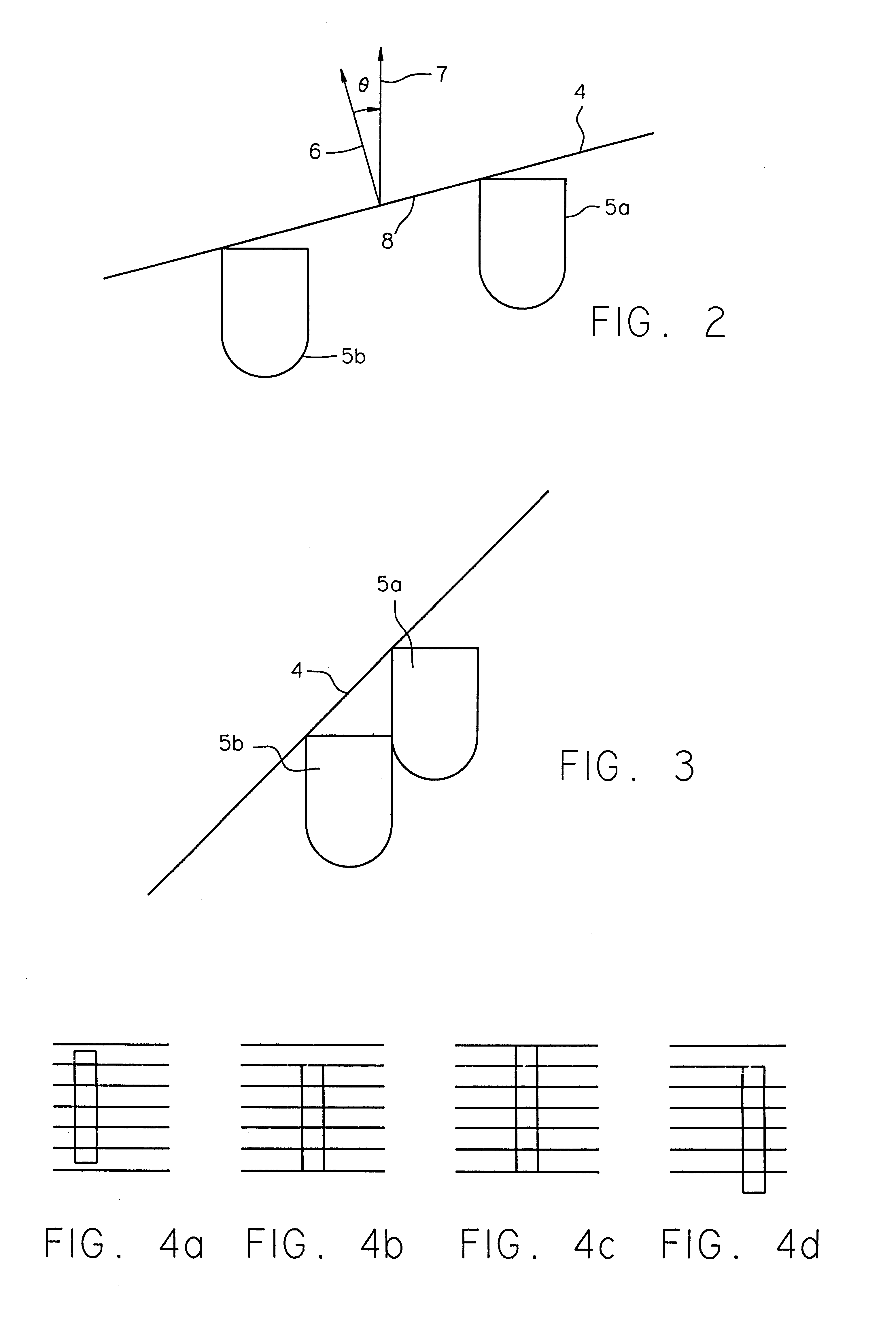
| angle | aaaaa | aaaaa |
| thickness | aaaaa | aaaaa |
Abstract
Description
Claims
Application Information