Electrically operated sprinkler

Inactive Publication Date: 2002-01-08
DAN MAMTIRIM ISRAELI PARTNERSHIP
View PDF4 Cites 23 Cited by
  • Summary
  • Abstract
  • Description
  • Claims
  • Application Information

AI Technical Summary

Benefits of technology

By employing two such motors, and controlling each one independently it enables to mai

Problems solved by technology

Due to the above there is loss of pressure, the efficiency of the sprinkler is affected, i.e., the outjetting wate

Method used


Image

  • Electrically operated sprinkler
  • Electrically operated sprinkler
  • Electrically operated sprinkler

Examples


Example

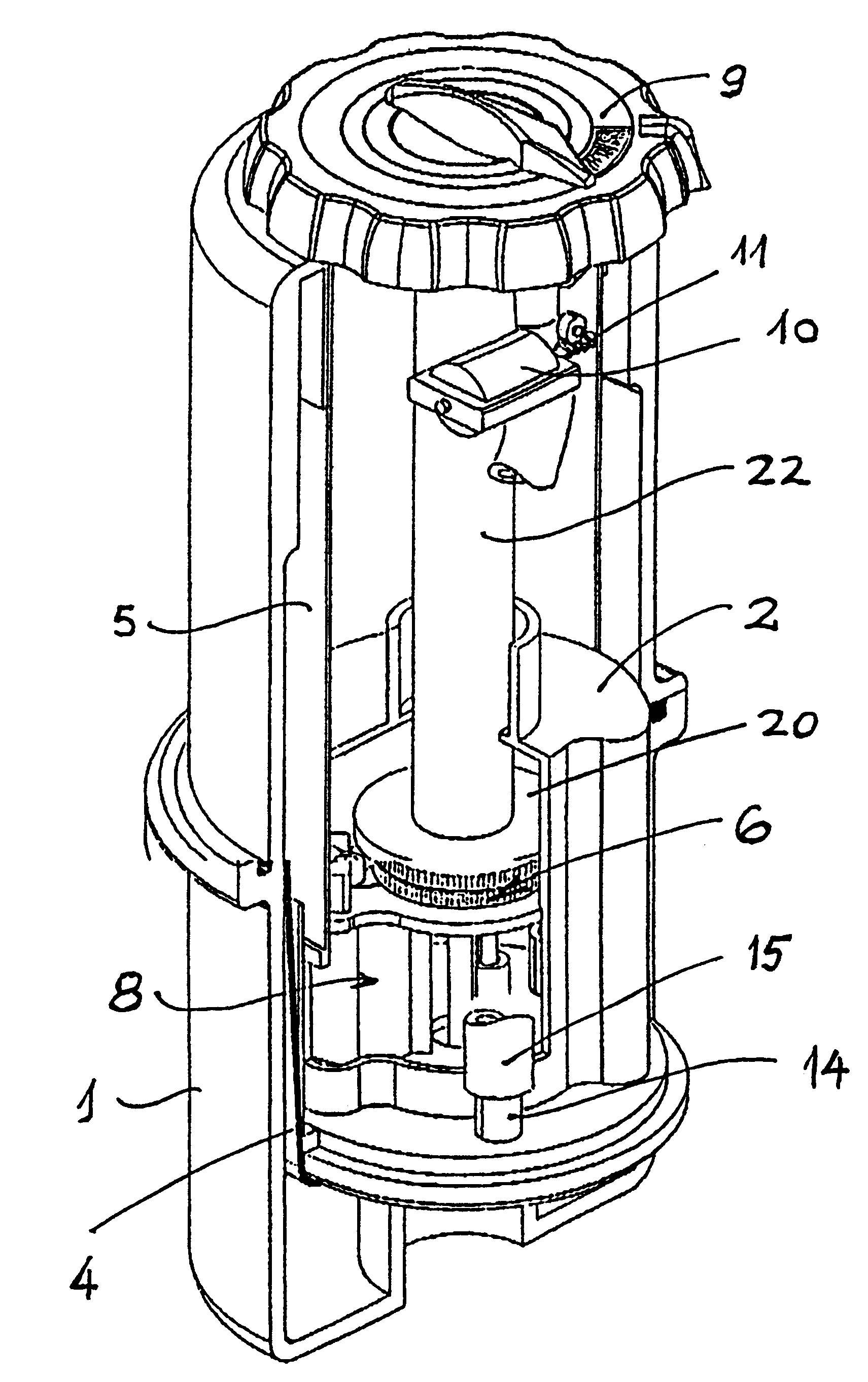
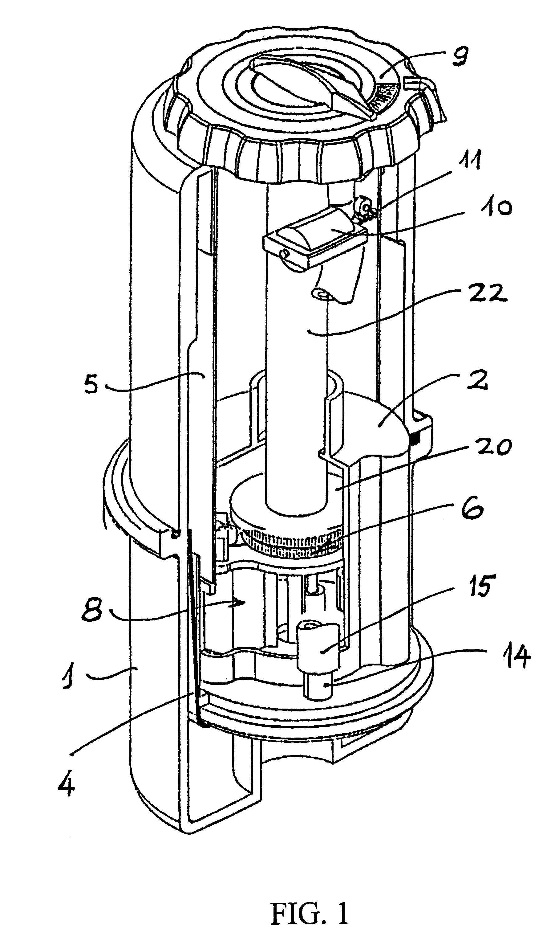
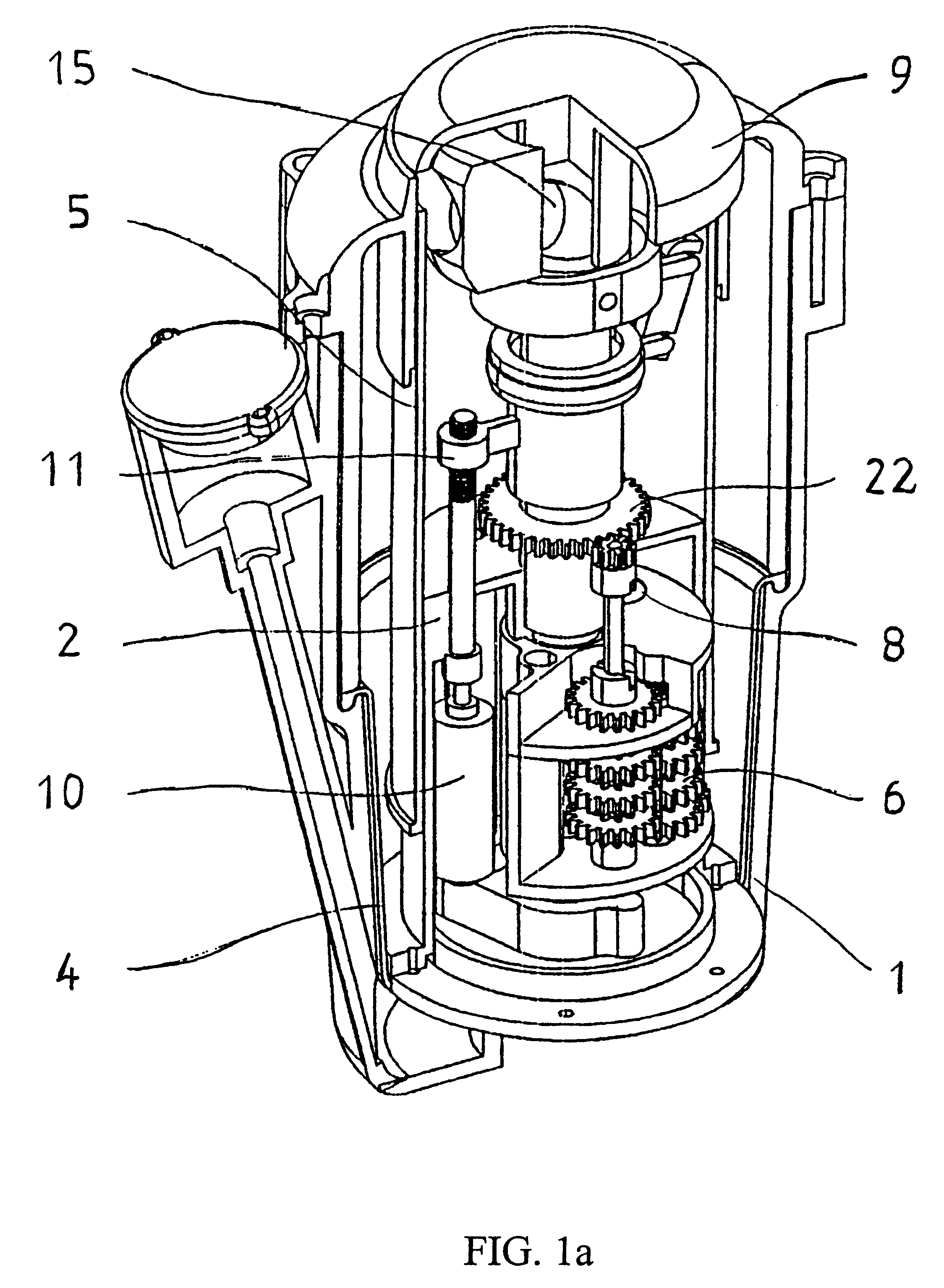
Turning first to FIG. 1 which is a perspective illustration partly in section of the sprinkler according to the invention.

Within housing 1 there is mounted a second housing 2, surrounded by sleeve 5 intermediate the two housings, there is provided a flexible membrane 4 forming a waterproof separation between the two housings. Alternatively a lip seal (not seen) is mounted. Within housing 2 there is provided a reduction gear mechanism 6 and an electric motor 8. Underneath cover 9 of the sprinkler or within the sprinklers housing there is provided a second electric motor 10 which is connected by connecting mechanism 11 to outlet nozzle 12. Outlet nozzle 12 is connected to inlet 14 by means of flexible hose 15, the water may however pass through central rotating part 22.

Turning now to FIG. 3. which illustrates the sprinkler in it's popped-out position namely housing 2 with sleeve 5 being pushed out of housing 1 by the water pressure acting on membrane 4 or on housing 2. The main tooth ...


PUM


Abstract

A rotary irrigation sprinkler head having a water inlet and a water outlet and a main rotary part. The main rotary part of said sprinkler head is provided with a gear and a plurality of toothed wheels forming a reduction gear, a first low voltage electric motor is provided connected to said reduction gear, the activation of said electric motor would revolve the sprinkler, and a second low voltage electric motor is provided connected to the outlet nozzle of said sprinkler adapted to control the angle of said outlet nozzle.

Description

The present invention relates to a rotary sprinkler and more particularly to electrically operated sprinklers. The sprinklers, according to the invention, could be for irrigating a full circular area or part thereof.There are known a large number of rotary sprinklers of all kinds of construction, sizes, etc. There is also known as what is described as "pop-up" rotary sprinklers which are housed in a housing unit buried in the ground adopted to pop-up when the water supply is turned on.The present invention relates to all kinds of sprinklers, however it is extremely useful for "pop-up" sprinklers, without excluding use of the invention with conventional rotary sprinklers.As is well known in the art, the rotary movement of the rotary sprinkler is obtained by what is known as water motors, namely, the water flow rotates the sprinkler head. It is well known that in order to achieve the rotary movement, some of the water energy is being used for obtaining the rotary movement of the sprin...

Claims


Application Information

Patent Timeline
IPC IPC(8): B05B15/00B05B3/02B05B15/10B05B15/74
CPCB05B15/10B05B3/021B05B15/74
Inventor KATZMAN, ODEDKATZMAN, ZOHAR
Owner DAN MAMTIRIM ISRAELI PARTNERSHIP
Why Eureka
Try Eureka