Transmission

Inactive Publication Date: 2002-01-08
LUK GETRIEBE SYST
View PDF7 Cites 23 Cited by
  • Summary
  • Abstract
  • Description
  • Claims
  • Application Information

AI Technical Summary

Benefits of technology

An object of the invention is to provide a continuously variable transmission which employs an integrated torque se

Problems solved by technology

A drawback of the aforedescribed continuously variable transmission is that the torque sensor and the mode of installing it in the transmission are quite complex and expensive.
Furthermor

Method used


Image

  • Transmission
  • Transmission
  • Transmission

Examples


Embodiment Construction

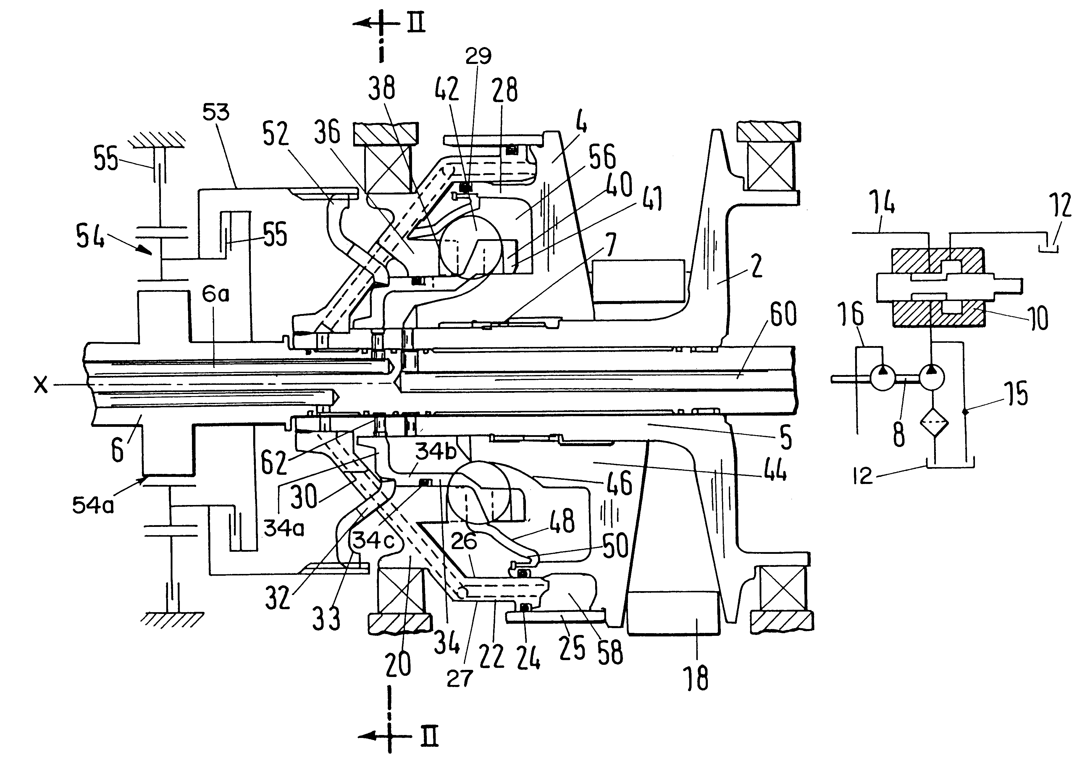
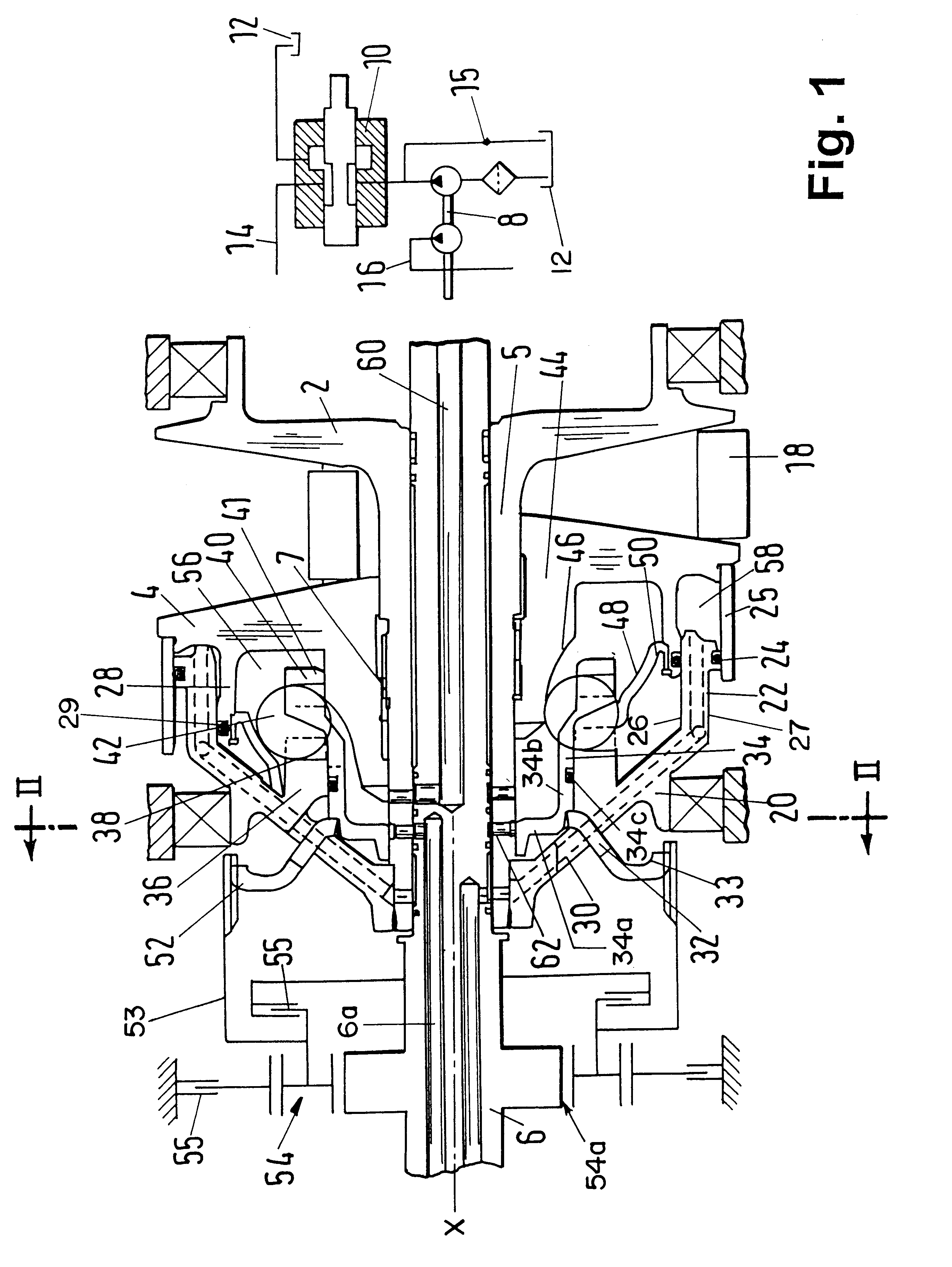
Referring first to FIG. 1, there is shown a portion of a continuously variable transmission (hereinafter called transmission or CVT) including a first adjustable pulley or sheave (hereinafter referred to as pulley) including an axially fixed conical flange 2 and an axially movable conical flange 4. The pulley of FIG. 1 receives torque from a prime mover, such as a combustion engine in the power train of a motor vehicle (see FIG. 1 of the referred-to '915 patent to Friedmann). The engine drives an input shaft (e.g., a camshaft or a crankshaft) 6 which is coaxial with and cannot move axially of a hollow shaft 5. The latter is rigid (e.g., of one piece) with the flange 2, i.e., the flange 2 cannot move axially of the shaft 5 and / or 6.

The flange 4 is movable (within limits) axially of the hollow shaft 5 toward and away from the flange 2 but cannot turn relative to the shafts 5 and 6; to this end, the flange 4 is provided with an internal gear 7 meshing with an external gear of the shaft...


PUM


Abstract

A continuously variable transmission with two adjustable pulleys and an endless torque-transmitting chain trained over the pulleys has a torque sensor which transmits variable torque from the rotary output element of a prime mover (such as the engine of a motor vehicle) to the axially movable flange of one of the pulleys. The torque sensor comprises one or more rolling elements and cam faces and/or guide surfaces which confine the rolling element(s) to movements radially and/or axially of the respective pulley. At least the rolling element(s) and those components of the torque sensor which define the cam faces and/or the guide surfaces of the torque sensor are confined in a fluid-containing plenum chamber adjacent the axially movable flange of the one pulley to thus achieve a pronounced reduction of space requirements of the unit including the one pulley and the torque sensor in the axial direction of the one pulley. The fluid in the plenum chamber serves to urge the axially movable flange of the one pulley against the adjacent edge face of the chain and to thus urge the other edge face of the chain against the axially fixed flange of the one pulley.

Description

The invention relates to improvements in transmissions, and more particularly to improvements in transmissions which constitute or resemble so-called continuously variable transmissions (CVT). Still more particularly, the invention relates to improvements in apparatus which can be utilized to transmit variable torque in transmissions of the above outlined character and embody so-called torque sensors.It is known to provide a continuously variable transmission with a mechanical or other suitable torque sensor which is (or can be) integrated into a pulley of the transmission. As a rule, the transmission comprises at least two pulleys which are mounted on discrete parallel shafts, and an endless flexible element (such as a belt or a chain) which is trained over the pulleys. Each pulley comprises a first conical flange which is rigidly affixed to (e.g., of one piece with) the respective shaft, and a second conical flange which is rotatable with the respective shaft and is movable axiall...

Claims


Application Information

Patent Timeline
IPC IPC(8): F16H55/56F16H55/32F16H61/66F16H61/662F16H9/18F16H9/00
CPCF16H55/56F16H61/66272F16H61/6625F16H61/662F16H9/00
Inventor SCHMID, JOCHENFRIEDMANN, OSWALD
Owner LUK GETRIEBE SYST
Why Eureka
Try Eureka